Steven, I was concerned about that as well. I think I will do exactly that and recess the gasket edge about 1/8". I actually think it will make a nice detail.
Ronald, yes, I was wondering about that as well. I originally had just top edges, but now I'm thinking that just floating the whole baffle on the front may be best -with either beveled or rounded-over edges. I'm still trying to come up with the best way to mount it. I do not want to screw into the plywood edge, that's out. I think I really need to make an inner lip and bolt to that. Perhaps with an internal aluminum frame to create a rigid bracing surface for the nuts. I would love to do the giant through bolts like on the Magico Mini, but that is a bit too complex and I believe it would require a very thick and rigid metal baffle in order to mount the baffle from only two points.
Ronald, yes, I was wondering about that as well. I originally had just top edges, but now I'm thinking that just floating the whole baffle on the front may be best -with either beveled or rounded-over edges. I'm still trying to come up with the best way to mount it. I do not want to screw into the plywood edge, that's out. I think I really need to make an inner lip and bolt to that. Perhaps with an internal aluminum frame to create a rigid bracing surface for the nuts. I would love to do the giant through bolts like on the Magico Mini, but that is a bit too complex and I believe it would require a very thick and rigid metal baffle in order to mount the baffle from only two points.
I wouldn't worry about the sides being tucked in, just the top and bottom because of the stacked construction.
I came to the same conclusion as you about not beeing able to hide the bolts. I do have rings between the bolt head and holes to decouple the baffle. The nuts I used are T- nuts pressed in a square piece of ply, glued in place with a flexible glue in my braces. You would have the room for an inner brace construction though.
I came to the same conclusion as you about not beeing able to hide the bolts. I do have rings between the bolt head and holes to decouple the baffle. The nuts I used are T- nuts pressed in a square piece of ply, glued in place with a flexible glue in my braces. You would have the room for an inner brace construction though.
Wow, I have a little time to chime in!
Thank You All for the design brainstorming on this thread. I will be getting my Vifa Array build under way soon, so I have enjoyed revisiting the concepts. I need thought provoking material to get me thru the long work weeks. 😉
I have a question in regards to driver mounting:
Some designers believe mounting the drivers flush with the baffle is the way to go.
However, I see the Vifa's of the two towers and the woofer of the Magico Mini has the drivers recessed behind the baffle, with the cutout rounded over. I understand why Ronald done this for this project, wanting the layer of extra damping and the awesome aesthetics. This is shown in the last three photos in post #2439:
http://www.diyaudio.com/forums/full...er-full-range-line-array-244.html#post4823566
As I have understood it, mounting the drivers behind the main baffle narrows the dispersion, although I can not say if it is too noticeable in this case.
Which is the more ideal way to go in terms of dispersion, defractions, and the such? Flush mounting or recessed with a round over?
The roundover I used in front of the drivers will act as a (very short) waveguide. The first time I saw member koldby's arrays I seriously started to consider using an aluminium baffle. However I wanted to make sure the performance potential would not be compromised. I started on a search hunt to see if someone had done something similar, documented with measurements. I found a member on a German forum who had done just that. I have linked to the graphs posted on that thread many pages ago. Sadly those graphs vanished over time. The thread was located here: ViFAST - für 50Euronen (SDS 5 1/4 + Vifa 9 BN 119/8) **fertig! Weiche S.3** - DIY-HIFI-Forum
I did look at the wayback machine results of his thread later on and was able to retrieve the flush mounted graph, sadly not the better performing "mit radius" graph.

The German text still confirms what I saw though...
He had a 9 mm radius on a 9 mm front baffle. It made a difference in the off-axis plots, actually improving them compared to the flush mounted driver. There was less difference between on and off axis SPL in the back mounted (those with roundover) plots. That was enough proof for me to go ahead. I decided on a 6 mm baffle with 8 mm radius. It had the best flow when looked at in a cross section.
No regrets here 🙂, I wouldn't have done it if I thought it had a compromised performance.

bündig eingelassen:
und jetzt mit radius, beide 0°:
-> mit radius leicht zappeliger
-> kontinuierliche aufladung relativiert schalldruckanstieg des chassis
-> als netter nebeneffekt wird das peak um 8khz durch die geometrischen maßnahmen entschärft
hier nochmal beide winkelmessungen gegeneinander
bündig eingelassen:
mit radius:
-> der schallwandbedingte bündelungseffekt zwischen 2 und 4khz wird deutlich entschräft
-> die nun entstandene relative senke bei 10khz wird energetisch unter winkel aufgefüllt
I did look at the wayback machine results of his thread later on and was able to retrieve the flush mounted graph, sadly not the better performing "mit radius" graph.
The German text still confirms what I saw though...
He had a 9 mm radius on a 9 mm front baffle. It made a difference in the off-axis plots, actually improving them compared to the flush mounted driver. There was less difference between on and off axis SPL in the back mounted (those with roundover) plots. That was enough proof for me to go ahead. I decided on a 6 mm baffle with 8 mm radius. It had the best flow when looked at in a cross section.
No regrets here 🙂, I wouldn't have done it if I thought it had a compromised performance.
Attachments

Last edited:
I do love the recessed driver look, my Raidho's are built that way as well.
Ronald, are you not using the mounting screws on the driver frame and instead just wedging the driver frame between the two aluminum baffle panels? What material are you using for the gasket between the aluminum layers and how thick is it? Do the bolts go through the countersunk front baffle, then the gasket, then the rear baffle, and then through the wood translam structure to a nut on the inside of the translam body (it is hard to see in your cross sections how the bolts connect to the translam)?
Thanks!
The drivers are mounted rigid, without any gasket to the inner baffle of 1 cm thickness.
As seen in this picture:

and this one:

The holes in the baffle for the enclosure mount are oversized to not touch the bolts that hold the outer baffle to the enclosure.
On the back of the inner baffle I glued on Mass Loaded Vinyl.

On top of that MLV layer I have neoprene that closes up the baffle to the enclosure.
I used to have MLV and neoprene between both aluminium baffles as well, but removed that later on and substituted it for Butyl rope.
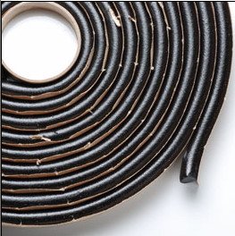
The butyl rope fills the space around the drivers, between the two aluminium baffle layers. The front gasket of the TC9 driver sits against the front baffle.
The countersunk bolts hold the entire baffle in place with a rubber O-ring between the head and outer baffle.
The bolts go trough oversized holes in the brace layer and lock into the square ply nuts (with pressed in T-nuts) instead of the square nuts seen here:

That's what the jig was for in this picture:

The home-made nuts sit in the rectangle opening seen here in the front:

In the back you can see the same jig, bolted to one of the braces. The nuts are glued in place with a flexible glue/sealant. The same sealant used to lock the threaded rods to the stack. This picture shows the nuts with the white glue/sealant:

That's how I build up the stack along the aluminium material that later became the inner baffle. It isn't bolted in place in this picture, just a piece of ply between the aluminium and the stack with some dowels in the holes of the brace. Everything held in place by the straps.
Basically I weighed down the drivers with the inner baffle bolted solid to them. That inner baffle "floats" between a layer of neoprene at the back and the drivers/butyl rope at the front.
Another look at the nuts:

The black half-round piece you see in the top brace is MLV, I decided to close the space between drivers with that MLV after reading something from Lynn Olsen. The terminals on the drivers each face that MLV piece, more breathing room around it, the MLV is 4 mm thickness.
The two tiny holes that can be seen in the brace are there for the internal wiring for the drivers.
The bigger breathing holes in the braces are in a different place for each subsequent brace (2 different types) to prevent one long hollow space throughout the entire enclosure.
The shape of the brace holes can be seen in this template:

As seen in this picture:
and this one:
The holes in the baffle for the enclosure mount are oversized to not touch the bolts that hold the outer baffle to the enclosure.
On the back of the inner baffle I glued on Mass Loaded Vinyl.
On top of that MLV layer I have neoprene that closes up the baffle to the enclosure.
I used to have MLV and neoprene between both aluminium baffles as well, but removed that later on and substituted it for Butyl rope.
The butyl rope fills the space around the drivers, between the two aluminium baffle layers. The front gasket of the TC9 driver sits against the front baffle.
The countersunk bolts hold the entire baffle in place with a rubber O-ring between the head and outer baffle.
The bolts go trough oversized holes in the brace layer and lock into the square ply nuts (with pressed in T-nuts) instead of the square nuts seen here:
That's what the jig was for in this picture:
The home-made nuts sit in the rectangle opening seen here in the front:
In the back you can see the same jig, bolted to one of the braces. The nuts are glued in place with a flexible glue/sealant. The same sealant used to lock the threaded rods to the stack. This picture shows the nuts with the white glue/sealant:
That's how I build up the stack along the aluminium material that later became the inner baffle. It isn't bolted in place in this picture, just a piece of ply between the aluminium and the stack with some dowels in the holes of the brace. Everything held in place by the straps.
Basically I weighed down the drivers with the inner baffle bolted solid to them. That inner baffle "floats" between a layer of neoprene at the back and the drivers/butyl rope at the front.
Another look at the nuts:
The black half-round piece you see in the top brace is MLV, I decided to close the space between drivers with that MLV after reading something from Lynn Olsen. The terminals on the drivers each face that MLV piece, more breathing room around it, the MLV is 4 mm thickness.
The two tiny holes that can be seen in the brace are there for the internal wiring for the drivers.
The bigger breathing holes in the braces are in a different place for each subsequent brace (2 different types) to prevent one long hollow space throughout the entire enclosure.
The shape of the brace holes can be seen in this template:
Last edited:
I found another picture showing the top of the inner baffle, when there was still MLV instead of butyl between the aluminium baffles:

That MLV layer has been removed (as well as the neoprene that was glued to the back of the outer baffle) and replaced/the space filled with butyl.
And last but not least: lot's of damping material inside:

The wool you see is ~7mm thick real wool felt, beneath it is fiberglass insulation filling the cavity. Impedance plots showed me how much fill I needed. The picture makes it hard to see, but there's still plenty of breathing space between the back of the driver and the wool felt.
Impedance of driver on baffle, no damping and final damping scheme using wool and fiberglass insulation:

(tests of the test enclosure with a single driver)
Impedance of the 25 drivers in the enclosure (blue curve):

The reddish curve was a first shot at a correction network, I removed the correction for the top end raise in impedance later on.
Fun to see the final impedance peak of the 25 drivers is at least as low as a single driver in open air.
(final) Correction network added later on:

Upper trace is phase, lower is impedance...
That MLV layer has been removed (as well as the neoprene that was glued to the back of the outer baffle) and replaced/the space filled with butyl.
And last but not least: lot's of damping material inside:
The wool you see is ~7mm thick real wool felt, beneath it is fiberglass insulation filling the cavity. Impedance plots showed me how much fill I needed. The picture makes it hard to see, but there's still plenty of breathing space between the back of the driver and the wool felt.
Impedance of driver on baffle, no damping and final damping scheme using wool and fiberglass insulation:
(tests of the test enclosure with a single driver)
Impedance of the 25 drivers in the enclosure (blue curve):
The reddish curve was a first shot at a correction network, I removed the correction for the top end raise in impedance later on.
Fun to see the final impedance peak of the 25 drivers is at least as low as a single driver in open air.
(final) Correction network added later on:
Upper trace is phase, lower is impedance...
Last edited:
WOW!
These posts reveal the true scope of detail put into your speakers. Absolutely incredible. And thank you again for sharing.
These posts reveal the true scope of detail put into your speakers. Absolutely incredible. And thank you again for sharing.
Thanks Ronald,
You have researched your ideas very thoroughly, which is why I figured You would be a good person to ask. 😉
Come to think of it, You bring up an important point: Matching the the On and Off Axis response as close as possible. I think this is more important then a "flat On-Axis" response, as we are EQing that anyway. With my current speakers, it seems the beaming of the high frequencies lends itself to a subjectively less spacious soundstage, but I have not proved this yet, so it stands as only a theory so far. I can not objectively test this until the On and Off-axis responses are more closely matched, which is not the case with the current speakers. 😱
I am hoping some time will open up soon for me to run some of these experiments myself.
As always, Thanks for keeping the fire alive.
Thank you both, for the kind words 
My project is incorporating everything "I think" is important in reproduction, based on everything I've read on the subject so far. From people like Dunlavy, Danley, Geddes, Toole, but also lots of opinions right here on this forum. I didn't take one opinion above another (for the most part) but tried to find common ground.
I'm only trying to find "my own truth" as to what's really important. It won't be everyone's truth though, I suppose. Somehow we are all on a journey to find our own mix of what works.
One thing I was dead set to try was phase linearity. That wasn't a common denominator at all. It still isn't, and probably won't be for a long time to come.
High on the agenda of only a few, like Dunlavy.
Even though I like what that does, I had to reset my believes after trying it. More and more I'm on the path to believe we humans pick up a lot of cues from comb patterns. We're also trained (during our lives) to ignore certain effects of that. Just record your precious sound at the listening spot and play it back on headphones. I bet you'll hear more room than you thought you had, sitting at your favourite sweet spot.
Right now I'm (still) revisiting Pano's Rephase shuffler with a twist. I'm listening to several tracks with a combination of the phase shuffler and my own cross talk experiments. All of these experiments are related to the effects of comb patterns. In fact, it's been the subject for me for quite a while.
I'm having a lot of fun listening so far. I still need more time and try more tracks. Isn't the fun (and enjoyment of music) the main reason to keep doing this? 😀 I could have build another set of speakers, but these arrays have shown me so many variations in sounds and staging, just by making small changes, I'm only just starting to connect the dots as to "what does what".
I hope you guys find your own truth, it's worth the journey! 🙂
Okay, much tweaking to the design -credit to all the great feedback from you guys!
I took Ronald's advice and left the top and bottom of the baffle opened. I also added about 1/32" on both sides of the baffle for a little wiggle room. The cabinet is massive, about 21" deep by 14" wide. It should be incredibly rigid with nearly 2" thick sidewalls and 1.5" tops and bottoms. The bracing is very heavy throughout. I'm still trying to figure out how to hide the bolt holes on top, but I'll work it out. The front with the cabinet edges is slightly bigger than the kit specified, the internal dimensions are an exact match.
I think the baffle mount should be particularly effective. I'm going to make an aluminum internal frame with a neoprene gasket for the inside of the cabinet. The baffle will be bolted to the aluminum butted up against the wood frame. I'll be able to make the bolt holes in the wood slightly larger to allow for some flex. I think this should create a nice float for the baffle and provide a very solid structure overall.
Please feel free to share your thoughts. I'm itching to start cutting wood!
Attachments

I don't really understand the value of the aluminium sub baffle as it will make construction much more difficult.
I would just use threaded insert nuts to mount the front baffle to the wood. Like these https://elraco.com.au/product_info.php/insert-nut-thread-8mm-overall-length-p-1120
These are much better than tee nuts and allow the baffle to be removed as many times as you like. Use the completed baffle as a template and mark the centres for the nuts with a transfer punch or brad point drill.
To cover the bolt holes you could either use a decorative top layer or even veneer. If you use nyloc nuts on the threaded rod you will only need to have access to the bottom ones to tighten.
I've got to agree with fluid here, The aluminium support doesn't seem to add to the construction, merely complicate it. In my baffle construction I wanted the baffle, holding the drivers to be separately floating and damped as to not excite the enclosure. The second layer of the baffle is a CLD construction. Here your aluminium support only supplies a rigid mounting point. It does not put pré-tension on the enclosure, like Magico did, you could put neoprene between the aluminium and the enclosure to have a damped structure holding the baffle though, was that the idea? Neoprene between baffle and enclosure, neoprene between aluminium and the enclosure and bolt that to each other... hmmm, that might make a floating, damped baffle construction.
Another thing that popped into my mind after seeing your sketch... complicating things further though... How about a shallow waveguide for that tweeter. Something the size of the cone of the woofer. It would provide time alignment between tweeter and woofer and support the bottom end performance of the tweeter. Preferably a bit oval to keep tweeter and woofer as close together as possible...

It would make it harder to construct though, and keep it beautiful.
But judging from the measurements Geddes did on the Behringers it might be worth the trouble, an older version of Behringers became quite famous (basically they are all cheap Genelec copies) in a certain listening test: http://www.diyaudio.com/forums/multi-way/177403-linkwitz-orions-beaten-behringer-what.html
Geddes had the results up on his website.
As to the bolts, I would use threaded rods and fix them on the top side, one layer beneath the top (the beauty layer) for instance by welding a rod or offset ring to it that can be fixed to that second layer of the stack.
Another thing that popped into my mind after seeing your sketch... complicating things further though... How about a shallow waveguide for that tweeter. Something the size of the cone of the woofer. It would provide time alignment between tweeter and woofer and support the bottom end performance of the tweeter. Preferably a bit oval to keep tweeter and woofer as close together as possible...
It would make it harder to construct though, and keep it beautiful.
But judging from the measurements Geddes did on the Behringers it might be worth the trouble, an older version of Behringers became quite famous (basically they are all cheap Genelec copies) in a certain listening test: http://www.diyaudio.com/forums/multi-way/177403-linkwitz-orions-beaten-behringer-what.html
Geddes had the results up on his website.
As to the bolts, I would use threaded rods and fix them on the top side, one layer beneath the top (the beauty layer) for instance by welding a rod or offset ring to it that can be fixed to that second layer of the stack.
Attachments

Yes, that is exactly what I was thinking -neoprene on either side of the wood cabinet frame. So baffle; neoprene; wood frame; neoprene; aluminum support.
Perhaps fluid is right with the insert nuts, at least for my first project. This would be much easier to build.
I think the waveguides are a bit too ambitious for this project. I'll keep that concept saved for future projects.
For the bolts, I was figuring I would secure the heads to the second layer down. Perhaps I would screw the top layer to the second layer from underneath with the bolts in place then assemble the layers upside down from top to bottom. Yup, that should work.
Time to start laying out my cut sheets and ordering some materials!
JRS,
since you have as many layers for the top section of the enclosure as you have thickness for the sides of the enclosure why not round over the top like the sides. Shouldn't be all that hard to do and it would also reduce the diffraction from the top edge like you have done for the sides.
since you have as many layers for the top section of the enclosure as you have thickness for the sides of the enclosure why not round over the top like the sides. Shouldn't be all that hard to do and it would also reduce the diffraction from the top edge like you have done for the sides.
JRS,
since you have as many layers for the top section of the enclosure as you have thickness for the sides of the enclosure why not round over the top like the sides. Shouldn't be all that hard to do and it would also reduce the diffraction from the top edge like you have done for the sides.
Though I agree from a diffraction standpoint I must say I've never seen that done (except for a horn) on a design like this and liked it aesthetically.
If I had to chose between a round-over on top and a shallow waveguide I'd pick the shallow waveguide. Especially after seeing the measurements of a Vifa XT on one of those Dave Pellegrene waveguides, combined with this design that could really be something...
I already love the XT tweeter line... Nahh.... I'm more than pleased with my Lines 😀. Can't say I wasn't tempted by the idea of building Synergies too.
In fact, budget and time permitting, having a dedicated listening room to play with I'd go with 5 line arrays and my own processing (I can't imagine needing 7 of them). What joy would that be! 😱 Throw in a big screen and a 3D capable projector.... though I hate to have to wear special glasses.
Years and Years of work to get that to perform in optimal condition

Last edited:
To try it I would get one of those waveguides from Dave Pellegrene. Just have it sit flush in a wood or corian baffle you could make a good looking baffle, I'm sure.
But because Dave makes it out of a relative thin material I would get in touch with him (he forms it out of sheet material) to try and get him to put a waveguide in a sheet the size of the entire baffle. Cut in the woofer opening, find a clever way to fixate it to the real back baffle and it would look stellar.
But as said, I'd first try it with a separate waveguide before committing to that second idea. And I'd damp the waveguide with the thickest automotive damping matt (CLD) I could find on the back side (butyl based of coarse).
Just googling on Dave's name and the XT tweeter shows pictures like this:

What's not to like? 😱
But because Dave makes it out of a relative thin material I would get in touch with him (he forms it out of sheet material) to try and get him to put a waveguide in a sheet the size of the entire baffle. Cut in the woofer opening, find a clever way to fixate it to the real back baffle and it would look stellar.
But as said, I'd first try it with a separate waveguide before committing to that second idea. And I'd damp the waveguide with the thickest automotive damping matt (CLD) I could find on the back side (butyl based of coarse).
Just googling on Dave's name and the XT tweeter shows pictures like this:
What's not to like? 😱
Attachments
![0-90+A%252B+Polar[1].jpg](/community/data/attachments/520/520018-4c3cc33b5be012b6596ab0dce1dc120d.jpg?hash=TDzDO1vgEr)
Last edited:
Pretty sure that Pellegrene Acoustics is no longer operating. Website domain inactive and facebook page hasn't been updated for a few years.
Parts express carries a fairly large selection of waveguides that would probably be OK or Troels gravesen has used some in his designs that should still be available like this one TQWT-
Parts express carries a fairly large selection of waveguides that would probably be OK or Troels gravesen has used some in his designs that should still be available like this one TQWT-
I figured that might be the case. I too had noticed an absence of his website.
Too bad though as the way he made those waveguides was pretty unique.
And the plots looked good enough to go try some 😀.
Maybe it's a challenge to do our own waveguides... Are you up for the task JRSystems? 🙂
There's still hope:
Posted here: http://techtalk.parts-express.com/forum/tech-talk-forum/68572-what-happened-to-pellegrene-acoustics
A year has passed though...
Too bad though as the way he made those waveguides was pretty unique.
And the plots looked good enough to go try some 😀.
Maybe it's a challenge to do our own waveguides... Are you up for the task JRSystems? 🙂
There's still hope:
Re: What happened to Pellegrene Acoustics??
Nice to be missed!
I'm doing fine. I had to shut down my website temporarily. I'm in the process of remodeling the downstairs of my house which is where I had my fabricating set up. So all my speaker and waveguide building equipment is packed away until I am finished. It was just to much work to try to keep up wth orders and work on the house. As I have mentioned before, my construction business has grown quite a bit in the last two years so it has eaten into my free time. I also got side tracked with the beautiful weather we have been having and took advantage of it to get some outside work done.
It has been nice to get a break from the waveguide business. I was really going at it hard for quite a while and I was starting to get a little burned out on it. Anyway I will still be checking in regularly and I will let everyone know when I have my new state of the art listening room up and running.
I'm pretty existed about getting it done.
Dave
Posted here: http://techtalk.parts-express.com/forum/tech-talk-forum/68572-what-happened-to-pellegrene-acoustics
A year has passed though...
Last edited:
- Home
- Loudspeakers
- Full Range
- The making of: The Two Towers (a 25 driver Full Range line array)