More or less. I imagine the acoustic suspension does a good job reducing the diffraction and therefore allows each to vibrate independently of one another. It's a very clever design, but it and VCAD can be a bit of a mystery when it comes to the details of design/simulation. Thanks for the answer, and sharing such a cool design.Does that answer your question?
Pardon me, but I don't quite get the use of the word diffraction in the above sentence. As I understand it, diffraction in the acoustic sense is the spreading of the waves around objects. Sharp corners can create secondary wave fronts that disturb the results and create an unbalance between on- and off-axis. Which is why I created a smooth variable radius enclosure as to have no sharp corners. The short waveguide in front of each driver further guide the waves that wrap around the enclosure. This is best seen in the ABEC simulations @fluid made of my enclosure shape, which he compared with a more regular shaped enclosure. The results can be seen starting here: @fluid ABEC simulations.
The vibration control I applied to the baffle has a couple of functions. I wanted to reduce the vibration entering the enclosure, hence the inner baffle that is floating between enclosure and outer baffle. The butyl rope has a three fold job to do.
I found Vituixcad to be quite accurate if I compare results of actual measurements to simulated results. Obviously it starts with the accuracy of the data that is put into Vituixcad. But the simulated data for these arrays corresponds quite well with what I've seen in practise. I highly recommend making use of tools like that to gain a better understanding of what is happening. It made a couple of light bulbs light up for me that I wasn't completely aware of. (thanks to @nc535)
The vibration control I applied to the baffle has a couple of functions. I wanted to reduce the vibration entering the enclosure, hence the inner baffle that is floating between enclosure and outer baffle. The butyl rope has a three fold job to do.
- it must damp the vibration of the inner baffle (and with that the driver frames) to minimise the energy that excites the enclosure.
- it must damp the vibration (eigen)modes of the aluminium baffle(s) itself.
- it acts as a CLD layer between the two aluminium baffles which helps achieve the above two points.
I found Vituixcad to be quite accurate if I compare results of actual measurements to simulated results. Obviously it starts with the accuracy of the data that is put into Vituixcad. But the simulated data for these arrays corresponds quite well with what I've seen in practise. I highly recommend making use of tools like that to gain a better understanding of what is happening. It made a couple of light bulbs light up for me that I wasn't completely aware of. (thanks to @nc535)

Then I'll explain more specifically what I'm describing. On a rectangular front baffle, like a standard MDF front baffle, the driver's physical location on the baffle changes the frequency response. I'm really just asking how or, now if this even applies to your build, given the way you've chosen to construct it with individual enclosures, mounted in a CLD style baffle you've described. In VCAD, I use this tool:


But I suspect based on what you've told me this doesn't apply to your design at all-- which is very cool, if that's true. That insight will probably influence my own designs going forward.
But I suspect based on what you've told me this doesn't apply to your design at all-- which is very cool, if that's true. That insight will probably influence my own designs going forward.
I see, these effects change with baffle size etc, but you could try and increase the edge radius and see if that smooths the horizontal output.
The upper driver which is closer to the edge suffers even more from these effects. However in a full line like mine, we don't expect to use the full range of the top and/or bottom driver anyway. In my case it's filtered with a low pass.
The results of my baffle diffraction are as follows:
With a rectangular shaped baffle, the horizontal variance would look like this:
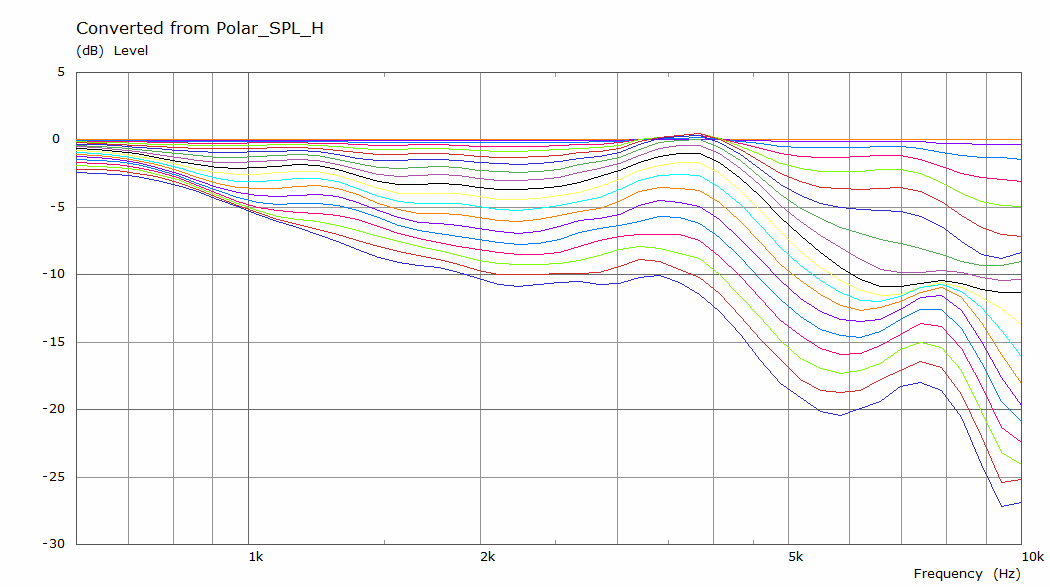
With my rounded enclosure shape, plus the fillet I put in front of the driver, it looks like this:
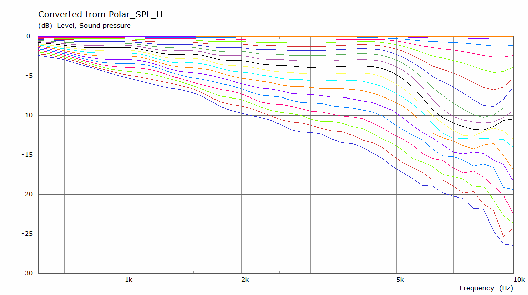
In this case, the on-axis output has been EQ-ed flat, but what's the key factor to get out of this is that the enclosure shape does have a large influence on the horizontal pattern we can achieve.
The enclosure shape combined with the baffle design made it act much like a waveguide, it shapes the output up to about 4 KHz and its still a lot smoother going up higher in frequency. That 'should' result in a good balance between the direct sound and the indirect sound coming back from the room. The resultant DI of the total speaker reflects that by looking like a smooth, line gradually increasing with frequency.

(red line in middle left graph)
What kind of project are you planning? I see some bigger drivers there on a 150 mm wide baffle... (in comparison the TC9 or Scan 10F only has 36,3 cm2 Sd).
The upper driver which is closer to the edge suffers even more from these effects. However in a full line like mine, we don't expect to use the full range of the top and/or bottom driver anyway. In my case it's filtered with a low pass.
The results of my baffle diffraction are as follows:
With a rectangular shaped baffle, the horizontal variance would look like this:
With my rounded enclosure shape, plus the fillet I put in front of the driver, it looks like this:
In this case, the on-axis output has been EQ-ed flat, but what's the key factor to get out of this is that the enclosure shape does have a large influence on the horizontal pattern we can achieve.
The enclosure shape combined with the baffle design made it act much like a waveguide, it shapes the output up to about 4 KHz and its still a lot smoother going up higher in frequency. That 'should' result in a good balance between the direct sound and the indirect sound coming back from the room. The resultant DI of the total speaker reflects that by looking like a smooth, line gradually increasing with frequency.
(red line in middle left graph)
What kind of project are you planning? I see some bigger drivers there on a 150 mm wide baffle... (in comparison the TC9 or Scan 10F only has 36,3 cm2 Sd).
Last edited:
The directivity effect of creating a line source swamps this out.But I suspect based on what you've told me this doesn't apply to your design at all-- which is very cool, if that's true.
Really I'm just planning on taking some of the enclosure advice I've learned over the last few years and upgrade some existing projects. I have a few 3-ways that could do with a more rigid enclosure, and those hard edges are really rough on the off-axis response. I want to isolate the mid/tweeter baffle from my woofer a bit in the future. Mostly I follow your project because it'sWhat kind of project are you planning?
1, really cool
2, involves 3D designed and CNC cut enclosures
3, shows a fantastic way of getting around a failure (when the whole thing split in two)
4, involves a lot of learning and practice that is relayed well to a layman
5, a really high quality build with some aspirational tools and techniques used (FIR, analog/digital x-overs, CLD, mixed materials)
6, explains in detail why it works so well together.
At some point I want to do an expanding array, or line source with some kind of full range or coaxial at the center. Most line arrays are shaded anyways, limiting their max SPL to the center driver's. Going for a wide dispersion and high SPL center section seems like a good way to optimize an expensive floor to ceiling tower, anyways.
...I will probably need a house first.
Believe it or not, no CNC tools were used in the production of these towers 😱.
It was all hand labor performed by a self proclaimed mad man 😉.
But thank you for those kind words! Much appreciated. 👍
It was all hand labor performed by a self proclaimed mad man 😉.
But thank you for those kind words! Much appreciated. 👍
Hi @Rigbaby, short arrays can be very directional at higher frequencies over it's length side, while being wide in the other direction.
Unless you use some type of shading.
See this example of an 8 driver TC9 array:

Sorry, didn't have a shorter array example ready. But it's easy to spot the differences in horizontal/vertical directions.
If you could use that behavior to your advantage, it might not be a bad idea.
Edit: I found one with 4 drivers:

See how it almost acts like a needle at higher frequencies? That makes it hard to be practical. Unless you shade them or use a Bessel type array.
(horizontal it will act the same as the one above it)
Unless you use some type of shading.
See this example of an 8 driver TC9 array:
Sorry, didn't have a shorter array example ready. But it's easy to spot the differences in horizontal/vertical directions.
If you could use that behavior to your advantage, it might not be a bad idea.
Edit: I found one with 4 drivers:
See how it almost acts like a needle at higher frequencies? That makes it hard to be practical. Unless you shade them or use a Bessel type array.
(horizontal it will act the same as the one above it)
Last edited:
Thanks for the response, I really appreciate your help and info! I recently picked up 12 of the TC9FD's on a pretty good deal and plan on getting another set as time and deals allow. I used your template to try a 6x arrangement that looked okay, but wasn't sure if it would be a wasted effort at that length. The limitations you referenced for the directivity is something you have mentioned in prior posts and it got me to thinking about a 5.2 mid height atmos setup where the line limitations might be used to 'shape' the height channels.
Here's a screenshot of the 6x, super new to the program so feel free to chime in if this isn't headed in the right direction 🙂
Thanks!!

Here's a screenshot of the 6x, super new to the program so feel free to chime in if this isn't headed in the right direction 🙂
Thanks!!
What's the dimensions, in inches? If it's in mm then the drivers wouldn't fit the baffle 🙂.
(if you right click in the schematic window you can choose: driver layout)
Can't quite figure out why driver D2 is connected in opposite polarity.
Here's an example of a driver layout with 80mm center to center spacing. (made for another thread)
You'd need about 84 or 85 mm center to center for the TC9 to make them fit.
Sure thing - I went with 100mm to 150mm spacing for the drivers (3.93", 5.90"), and tried to move them up to where they might be placed on the wall using the driver layout tool. The driver polarity was something I picked up in another thread here (Patrick was looking at bessel array's and the effect of a polarity flip on the vertical and horizontal responses).
Here is the layout:

Here is the layout:
So it was a Bessel after all, except at low frequencies, well, aside from the inverted driver.
Would you ever consider a project like this "finished" @wesayso?
I once stated I was finished. But in all honesty, this has been like a "lab project" for me. Just trying to learn from it and learn how and what we perceive in a room. Trying to connect the dots of what I can measure and what I perceive. So it's been a fun ride and it isn't over yet.
And would you ever consider doing a writeup on it like many well-known DIY kits have?
I once started a complete write-up of this build on: https://www.vandermill-audio.nl/ but never finished it. Lots of instances where "regular life" got in the way of things. Had a bit of bad luck with my health and it slowed things down drastically.
I can't stop thinking about how we're almost at page 400.
Sorry for that, writing it all up and getting feedback has worked well for me as a motivator to keep going.
Originally, I wanted to be as open and transparent as possible about the things I do or find out along the way. Meaning that this audio game can be very secretive and even has a lot of myths going on. By being more open (sharing bot successes and failures) and trying to work together I believe we, as DIY aficionado's can advance this hobby and the end result should be more people enjoying the fruits of their labor.
I feel I've gotten back just about as much as I've put into this hobby. The interactions with fellow members, too many to mention, has resulted in a better understanding of what really is happening with speakers inside a room for me. I've learned so much on this forum and I guess that has resulted in me rambling on 😀.
Tools like REW, RePhase, DRC-FIR, Vituixcad, (and many more for several other purposes) made available for free has been a blessing for us DIY folks. As are the pro guys that willingly have shared their experience. But also the fellow DIY fanatics willing to learn/find out the rules of the game.
Still searching for ways to be able to use the Lexicon PCM plugins again. I think I found a way, or at least partially.
It looks like I can use it fine as a plugin within JRiver without losing the settings. So in that case the faulty combination seems to be Metaplugin/Lexicon PCM.
For some parts of my use I can find ways around it. I'll know if it works in a few days after testing it a bit more.
Its use as a stand in shuffler worked well, if I can get that back I'd be happy.
Hi @wesayso, I’ve just seen this and thought it might be of interest: Schiit SYN
Looks to be an analog matrix with knobs to dial in the ambient effects.
Looks to be an analog matrix with knobs to dial in the ambient effects.
Thanks fort the heads up, but I'm already using my own extraction mix or matrix for my goals (which work well enough to stick with it 🙂).
I'll let this wonder of a machine for others to dive in. 😀 After reading that first page, you'd have to be crazy not to order one right this minute 😉.
I'll let this wonder of a machine for others to dive in. 😀 After reading that first page, you'd have to be crazy not to order one right this minute 😉.
- Home
- Loudspeakers
- Full Range
- The making of: The Two Towers (a 25 driver Full Range line array)