Has anyone heard of the Eventide Omnipressor? I'm curious because it could make for an interesting compressor discussion but I'm not sure what Forum it belongs in. I reverse engineered Walter Becker's personal unit and built my own version and demonstrated it for one of Walter/Donald's producer friends and he liked it better than Walters. It was fun to take a deep dive into such a weird compressor.
 This also gets into a discussion about VCAs and I find that pretty interesting too.
I'd be interested. I happen to like the effect and especially how the envelope time constants seems to influence what I do when playing through one. As far as VCA's go, I'm afraid I cant be much help beyond a Vactrol or CA3080 trans amp chip. I also have some GE H11F1 FET output optocouplers, which I havent attempted to use for controlled attenuation yet. Because in my application, the signal voltages are just too high for its 30V kapow-point.
I see the VCA along with time constants of "attack" and "decay" from an analog synth perspective. In a tube guitar amp I'm presently working on, I try to get the signal envelope at the input jack, then use it to modify the far more clipped signal down at the end of the chain.
I'm waiting for my head to conceive how to do a resistor "power soak" that works like a compressor, so I can get the output tubes / tranny within the effect. Which would be much more like a synth, with its constant amplitude VCO that's later VCA'd...
Well this is interesting, I didn't expect such a response and so soon. Cool! I will continue with the idea and get my files together etc.. I have lots of interest in getting my compressor projects in general back on track. I have my versions of several including the Fairchild which needs some updating. The Omnipressor was a very finished one to the breadboard level and still on loan. I want to get that into a finished version.
I also did a remarkable OTA based guitar compressor that is way too fast and smooth to tell that it's working. It also reaches 200:1 at the top of its dynamics. I have only built one of these and it went into one of my production amps a few years ago. I have a demo recording that used this compressor to do a vocal/acoustic guitar test with a single vocal mic situated 3 feet in front of me sitting in a chair with the guitar in hand. It's weird to imagine the setup when you listen to it because my wife is doing dishes about 15 feet away behind the mic and it gives some idea of how crazy this compressor is. The guitar and the vocal strangely seem to mix to well for that distance and very non-ideal situation. When my wife bangs around in the kitchen it sounds like it's right there. Very cool circuit. It's based on one of my discrete transistor OTA based VCAs and very Fairchild like.
I also did a remarkable OTA based guitar compressor that is way too fast and smooth to tell that it's working. It also reaches 200:1 at the top of its dynamics. I have only built one of these and it went into one of my production amps a few years ago. I have a demo recording that used this compressor to do a vocal/acoustic guitar test with a single vocal mic situated 3 feet in front of me sitting in a chair with the guitar in hand. It's weird to imagine the setup when you listen to it because my wife is doing dishes about 15 feet away behind the mic and it gives some idea of how crazy this compressor is. The guitar and the vocal strangely seem to mix to well for that distance and very non-ideal situation. When my wife bangs around in the kitchen it sounds like it's right there. Very cool circuit. It's based on one of my discrete transistor OTA based VCAs and very Fairchild like.
Attachments
Last edited:
Well, that's certainly better than I can play / sing it. If you were nearby, I'd ask for lessons!
Anyway, it's remarkable how compression does give that studio sound. There's a lot of that "We shape out tools and thereafter our tools shape us" in that, me thinks. (Attributed to preservationsound.com)
No matter, I like it. I have fun with it. The Behringer mixer someone bought for the coffee house I do open mics at has compression on 2 or 4 channels, but they dont use it; I assume they dont know how. They had me cranked on the vocals last night, said "so they can hear me". I noticed I couldnt drive the volume down any; just got even louder the closer to the mic I went. I honestly thought I blew a couple right out of the place, as I looked up after a few songs and they were gone. Another musician later assured me that didnt happen...
Years ago I played bass through an MXR Dynacomp. I loved how I could just hang onto a note at full volume - the additional lat-it-tude it gave me in the temporal dimension. Maybe a tool shaping me, but why play two notes when you can just just sail one right across that span of time?
Looking forward to the conversation! Hopefully I can learn something about VCAs and the circuits that control them in a compressor context.
Oh, BTW I'm also a fan of multiband expansion of commercially recorded material, which I guess isnt all that popular - remember DBX 3BX? I have played some with Reaper's ReaComp plug-in, where they let you go into fractional compression ratios, instead of limiting the bottom end of the ratio control at "1". I assume most programmers would say "Why would you ever want to go below 1?!"
The DBX 3BX is one of those classic DBX devices that uses a version of the discrete Blackmer VCA that the Ominpressor is based on. Around 1970 David Blackmer took the existing two-transistor log-antilog circuit to another level by putting them back to back and forming a VCA. That is what all of the old DBX processors and the Omnipressor are based on. Richard Factor from Eventide knew David Blackmer and they came up with the idea together. There's also an interesting RMS detector involved and I have a version of that too.
That VCA was made by hand picking transistors to match Vbe well enough to do this and then to keep them happy together thermally they were set into a ceramic Beryllium carrier with wax. I learned all about this when working on Becker's Omnipressor and had the idea that this could be done differently today. A side not here is that the very misunderstood heat sink grease was often substituted in these and ruined the performance. I have replaced many a blown power transistor because people do not understand that if you can see heat sink grease, there's WAY too much and will actually reduce the thermal coupling. The Blackmer VCAs can't use it at all. It's a disaster.
If you take the Blackmer design and instead use surface mount dual transistors, it all gets far simpler. They still need the same calibration and have quite a bit of sensitivity to the transistor type, which affects noise and distortion, but what you end up with is a VCA that costs $0.50 instead of the $8.00 to $12.00 or more that the modern IC versions go for. Interesting stuff for sure and guitars are lovers of low order distortion making it all less critical for guitar use. I have made discrete Hi Fi versions however.
The Blackmer VCA I did for the Omnipressor, but now my favorite VCA is OTA based which is what the 3080 is. Despite the misunderstanding of the language that's very common in the guitar world, these are in fact VCAs. VCA is simply the generic term Voltage Controlled Amplifier and OTA is the specific circuit, Operational Transconductance Amplifier. Just for clarity in the discussion") Another way to put it is that the VCA is an application of the OTA. I will get into some details about why the OTA VCAs that I build and use now are far better than the 3080.
Another way to put it is that the VCA is an application of the OTA. I will get into some details about why the OTA VCAs that I build and use now are far better than the 3080.
Regarding the test track, it wasn't meant to be a performance, but it's somehow pretty good. It's one of the songs I play with my wife on bass. We call act The Retrofiers and some day perhaps when we move back to Port Townsend we will do it again.
And multi-band expansion? Wow, I haven't gone there yet. If you are using Reaper, that's a good place to experiment with it. I love Reaper, it's a great low cost DAW for sure.
I attached another sample recording that's releveant to my Fairchild style feedback compressor. This track was a deliberate attempt to force artifacts to study. Both my guitar(Tele) and vocal are going through a ridiculous 20:1 ratio to hopefully produce a disaster to show me what characteristics to focus on. The surprise was that although it is not right, it isn't the horrible recording I was trying to get. Very interesting. This gets into Rein Narma and the history of the Fairchild compressor. I reverse engineered that one too and it's an ongoing project
That VCA was made by hand picking transistors to match Vbe well enough to do this and then to keep them happy together thermally they were set into a ceramic Beryllium carrier with wax. I learned all about this when working on Becker's Omnipressor and had the idea that this could be done differently today. A side not here is that the very misunderstood heat sink grease was often substituted in these and ruined the performance. I have replaced many a blown power transistor because people do not understand that if you can see heat sink grease, there's WAY too much and will actually reduce the thermal coupling. The Blackmer VCAs can't use it at all. It's a disaster.
If you take the Blackmer design and instead use surface mount dual transistors, it all gets far simpler. They still need the same calibration and have quite a bit of sensitivity to the transistor type, which affects noise and distortion, but what you end up with is a VCA that costs $0.50 instead of the $8.00 to $12.00 or more that the modern IC versions go for. Interesting stuff for sure and guitars are lovers of low order distortion making it all less critical for guitar use. I have made discrete Hi Fi versions however.
The Blackmer VCA I did for the Omnipressor, but now my favorite VCA is OTA based which is what the 3080 is. Despite the misunderstanding of the language that's very common in the guitar world, these are in fact VCAs. VCA is simply the generic term Voltage Controlled Amplifier and OTA is the specific circuit, Operational Transconductance Amplifier. Just for clarity in the discussion
Another way to put it is that the VCA is an application of the OTA. I will get into some details about why the OTA VCAs that I build and use now are far better than the 3080.Regarding the test track, it wasn't meant to be a performance, but it's somehow pretty good. It's one of the songs I play with my wife on bass. We call act The Retrofiers and some day perhaps when we move back to Port Townsend we will do it again.
And multi-band expansion? Wow, I haven't gone there yet. If you are using Reaper, that's a good place to experiment with it. I love Reaper, it's a great low cost DAW for sure.
I attached another sample recording that's releveant to my Fairchild style feedback compressor. This track was a deliberate attempt to force artifacts to study. Both my guitar(Tele) and vocal are going through a ridiculous 20:1 ratio to hopefully produce a disaster to show me what characteristics to focus on. The surprise was that although it is not right, it isn't the horrible recording I was trying to get. Very interesting. This gets into Rein Narma and the history of the Fairchild compressor. I reverse engineered that one too and it's an ongoing project
Attachments
I'd like to know about that. Not that I'd be any competition; I've played around with the 3080 since the late 70's and havent designed a single thing in the commercial audio effect / stomp box space in the last 50 years - I highly doubt I'd start up an audio business now at 67...I will get into some details about why the OTA VCAs that I build and use now are far better than the 3080.
But I still like to understand how things work and what makes things work better. An example might be the manufacturer touted Rane limiter, as endowing their amplifier with the title "Loudest 100W amplifier in the world". I sliced it out of their op-amp salad schematic, getting it out of the eye bleach chart realm;
Like a kid, I can point to the "envelope follower", the resistors determining attack and decay, the FET element that changes the Z1 B op-amp gain. What I dont understand is the function of Z2 A. Did they have an extra op-amp floating about and decided might as well use it for something? Is it some kind of second harmonic generator? Why would (whatever it does) be desirable in a commercial PA amplifier?
Anyway, I'll likely be dropping more schematics here, mostly for the sake of understanding "How It Works", like the old side-bar in Popular / Radio Electronics magazine projects used to have.
You mentioned the Fairchild compressor, this one?
An amusing bit of circuit, using 6V6s to drive the DC envelope part, that in turn changes the gain of the 6386 tube string. I'm pretty sure those tubes wouldnt work arranged single ended which is part of the reason for all the transformers, which I take it arent just for balanced line compatibility. I read that such a solid, hard drive to the rectifier / filter is what gave it a lightning fast response.
When I look at it, I see Guitar Amplifier with a side chain AGC, rather than an AGC, with its "Control" fed by a side chain power amplifier. I find it hard to believe for as long as the device has been in existence, no one else has seen it in that way. I have a Bogen tube amp with an independent 70V winding, which could feed the full wave bridge while having the speaker connect to the 0-4-8-16 outputs. Knowing such an OPT existed, one would think someone would have thought: Hmmm?
Anyway, last night I was playing a nylon guitar with a OEM Shadow pickup through my ART rack dual compressor (one side for guitar, one for vocal), where I like to over-do-it on the ratio, to where I almost get reverse envelopes on every string pluck. Still surprise myself in how quickly I recognize the availability of the additional sustain - and use it musically.
I'll be waiting to hear that story.This gets into Rein Narma and the history of the Fairchild compressor
Last edited:
Has anyone heard of the Eventide Omnipressor?
Hi, i'm old enough to have seen some in studios i worked in, but young enough to have never heard them used as they were replaced by 'plug ins' clone at that time or had maintenance issues... namely vca's becoming noisy iirc.
I think there was some guys which moded them with 2150 but not sure 100%... it was 20 years ago and i wasn't as much tech nerd as i'am now.
Is this one a feed forward sidechain ( or a mix of forward/backward)? I suppose it's in the sidechain the 'character' of the unit is. From my experience with solidstate it's most often the case ( dbx165, GML, SSL 4000 mixbus variants,...).
What makes it an interesting unit from your pov?
JJ,
The schematic linked is from 660, the mono version of 670. There is differences between both units : biasing shem of 6386 is different, transformers used too as 670 allowed for MS matrixing through them. There is a difference in overall gain of circuits too, 660 having more (16db vs 7db iirc).
Their targeted use was different too as 660 was more seen as an instrument compressor/limiter, 670 was most often used in front of either transmitters ( radio station) or cuting machine ( for vinyl production).
You are right variable mu design ( tube comp) are 99% of time push pull circuits. It's relative to 'thump' happening, it helps reducing this. I think i remember some people experimented with non push pull config without this much success back in the days at prodigy-pro.com's forum.
You are right about the big sidechain amplifier: 30w rms tube amp needed for such time constant as the one used in 670.
It's needed as the limiter target was to protect the cuting head ( or transmitter amp) from transients so it had to be very fast attack while retaining enough energy to allow for 5sec/20sec release time from a very short peak all this driving 8 grids in //.
Funny you see it as a guitar amp though, the audio part of the circuit is way simpler as a single stage common grounded cathode amplifier ( // 6386 makes for one single stage). The genius of Narma was into the sidechain design imho, as it offered a way to have treshold and ratio availlable ( dc threshold) and satisfied the technical requirements regarding envelope time ( vari mu are most often way slower...).
Psu is often overlooked for this units too. It should'nt: Narma implemented a fully tube regulated psu on 670. It's part of the sound. Funny enough you'll find it implemented in most researched varimu eg from Urei 17X familiy where a (crude) shunt regulator is used to power the gain reduction cell ( an Oa3 which feeds 6bc8)...
There had been variation around the 670/660 during the years, some very clever: T. DeParavinici ( EAR) had the idea to implement the architecture with different tubes for audio ( pcc189~ 6bc8) in cascode for gain reduction/amp cell ( cascode makes for extended freq response in highs) with a solid state sidechain ( retaining the clever threshold arrangement): sounded blissfull ( in fact i prefered Ear 660 to 'real' Fairchild 660/670 i've heard) and makes for 1/8 ratio for bulkness/weight, easier for maintenance,...).
If you want to implement such a circuit as a 670/660, target something which will give 100v at max post sidechain (driving the rectifier before rc timing network) to approach a 'real one' behavior... should be in ballpark.
Want to know more about 670 and Rein Narma: member CJ (at prodigy-pro.com forum) made an interview with him some 25 years ago. He explained the full story, technically related info and other things ( how they modded Neumann U47 tube to cathode followers because they had too much gain for the use they had of it on movie...).
It must be availlable in the 'schematics/technical library' of the forum ( you need to be registered to have access). I might have it on an HDD somewhere too if you don't find it and are interested in it...
Last edited:
OK, you guys are doing what I hoped that you would, show some serious interest! I have been away from my compressor work for a few years and I want to dig it out and get some portion of my ridiculous multi-task of a work schedule working on compressors. It's a challenge to divide the time.
I think that you both have raised so many good points that I should take it one at a time and then get some documents together later to get this party started. I will be back today some time with some good stuff.
And by the way jjasniew, 67 is no time to hang it up, but I don't know the whole story of course. I'm just a kid at 61 so I'm one to talk. I joke about my age with friends but I'm also serious about playing guitar, violin, and singing at my 100th birthday. I also plan to never stop working. I do have my independence however having retired from industry in 2006. Running my own ship is so much better. This is a time in my life to build and restore the fun stuff while helping others learn and hopefull they will show me a thing or two now and then.
I have always had respect for the RANE people for putting out some nice gear and being one of the best resources for technical articles etc.. They also, at least back when I frequented their site, published their schematics. That limiter is a good example of how they make use of some apparently simple circuits that always seem to be done well. The buffer Z2 looks like a gyrator but I think that it modifies the dynamics and possibly compensates for some shortcummings of the FET. I will run a simulation to get some details. The first clue is the 9.4 mS ish time constant of the circuit. The simulation will make it clear. Simulations are a BIG hlep for truly understanding compressors with all of the crazy dynamics involved. They also save so much time that would otherwise be wasted with manual mathematics. The power of computers...
This limiter potentially causes some serious distortion unless... it's set up to never hang out between limiting or not. I'm guessing that RANE designed this circuit to be completely off until it's time to prevent clipping. That is how you get away with such a simple circuit that would not work so well if it were trying to be a Fairchild which is also a feedback limiter but has a wide soft dynamic range that an FET could never handle. The claim to be the most powerful 100 Watt amplfier is cute and true. If you get rid of that pesky headroom problem, the average power goes WAY up. That's another rabbit hole.
I will have a closer look at the RANE circuit and it may prove interesting.
The example below shows the Omnipressor upon attack of a 40 Hz sine wave while in compression mode. It's a great thing to study being such a wild and wooly compressor. This is a also a good exampe of all of the crazy signals going on in an Omnipressor to get the job done. This isn't meaningfull without some schematics and explanation of course and I will get into all of that as I find time.

Regarding the Fairchild. That is the schematic that I used. The 660 is what I was after and long story short, like so many of my other circuits that derive from tubes, I found out that the tubes have almost nothing to do with how it sounds and certainly not the power supply. The guitar amplfier and pedal markets suffer from so many misconceptions about tubes that I'm finding it pretty ridiculous these days. I do enjoy making tubes from transistors and learning why this is not generally understood. FETs are yet another very misunderstood area and yes another giant rabbit hole of discussion.
More later...
I think that you both have raised so many good points that I should take it one at a time and then get some documents together later to get this party started. I will be back today some time with some good stuff.
And by the way jjasniew, 67 is no time to hang it up, but I don't know the whole story of course. I'm just a kid at 61 so I'm one to talk. I joke about my age with friends but I'm also serious about playing guitar, violin, and singing at my 100th birthday. I also plan to never stop working. I do have my independence however having retired from industry in 2006. Running my own ship is so much better. This is a time in my life to build and restore the fun stuff while helping others learn and hopefull they will show me a thing or two now and then.
I have always had respect for the RANE people for putting out some nice gear and being one of the best resources for technical articles etc.. They also, at least back when I frequented their site, published their schematics. That limiter is a good example of how they make use of some apparently simple circuits that always seem to be done well. The buffer Z2 looks like a gyrator but I think that it modifies the dynamics and possibly compensates for some shortcummings of the FET. I will run a simulation to get some details. The first clue is the 9.4 mS ish time constant of the circuit. The simulation will make it clear. Simulations are a BIG hlep for truly understanding compressors with all of the crazy dynamics involved. They also save so much time that would otherwise be wasted with manual mathematics. The power of computers...
This limiter potentially causes some serious distortion unless... it's set up to never hang out between limiting or not. I'm guessing that RANE designed this circuit to be completely off until it's time to prevent clipping. That is how you get away with such a simple circuit that would not work so well if it were trying to be a Fairchild which is also a feedback limiter but has a wide soft dynamic range that an FET could never handle. The claim to be the most powerful 100 Watt amplfier is cute and true. If you get rid of that pesky headroom problem, the average power goes WAY up. That's another rabbit hole.
I will have a closer look at the RANE circuit and it may prove interesting.
The example below shows the Omnipressor upon attack of a 40 Hz sine wave while in compression mode. It's a great thing to study being such a wild and wooly compressor. This is a also a good exampe of all of the crazy signals going on in an Omnipressor to get the job done. This isn't meaningfull without some schematics and explanation of course and I will get into all of that as I find time.
Regarding the Fairchild. That is the schematic that I used. The 660 is what I was after and long story short, like so many of my other circuits that derive from tubes, I found out that the tubes have almost nothing to do with how it sounds and certainly not the power supply. The guitar amplfier and pedal markets suffer from so many misconceptions about tubes that I'm finding it pretty ridiculous these days. I do enjoy making tubes from transistors and learning why this is not generally understood. FETs are yet another very misunderstood area and yes another giant rabbit hole of discussion.
More later...
Giving that Rane circuit a bit more thought, I'm thinking that it's as obvious as it looks. Z2 is simply gives a buffered AC coupled positive feedback that shortens the attack time. I will verify and quantify this with a simulation, but this is what it looks like. There's nothing like seeing the timing plotted an we shall see.
I will get into some details about the Fairchild later as well, but one thing I can say now is that the balanced nature of things in the Fairchild is indeed all about supressing the control voltage. This is one of the important qualities of these that gave them such a reputation.
I will get into some details about the Fairchild later as well, but one thing I can say now is that the balanced nature of things in the Fairchild is indeed all about supressing the control voltage. This is one of the important qualities of these that gave them such a reputation.
Here's the compensated OTA based VCA that I'm enjoying these days for guitar related thingies. It's a completely public domain circuit that doesn't get the attention that it deserves in my opinion. I have some compressors based on this concept that are pretty mind boggling when all of the other pieces are in place.
The first thing to consider while trying to understand circuits like this is that there is no hfe. Bipolar transistors do not have a "current gain". It's just a leakage and should not even appear in most equations. I have seen some people that I respect a great deal being completely mislead as to the operation of some circuits by falling for the hfe myth. In fact I have seen evidence of this confusion in countless commercial schematics dating from the 1950s to present. It's become something of a hobby to correct or find better approaches to these wayward circuits. It's fun. It's also fun to see how well some apparently bad circuits can work. You just cannot know it all.
This nifty VCA is in my opinion what 3080s should be replaced with. It's also a perfect example of a 60 year or thereabouts old circuit that collects dust becuase its performance depends on the transistor quality and thermal coupling. These problems are solved by several dual surface mount devices that now can be had at very low cost. The Blackmer VCA is the same way. By using modern dual transistors and op-amps, very small DBX style VCAs can be built and one example that I built used a mere $0.50 in parts at quantity. It's worth diging up circits that had restrictions in the past but no longer do.
The magic with this VCA is that the very fundamental OTA is fed by a circuit that produces the opposite distortion and it cancels. This is possible because BJTs have very reliable characteristics as described by the Ebers-Moll equation and modern transistors obey it quite well. I mostly use this for guitar related work so 1% resistors do the job but things can be optimised better for a Hi Fi version although this isn't the approach for that in many cases. Mind you the distortion is less than most tube power amps so it is pretty useful. I have had this simple version running 0.1% at full output and only using the 8 Volt power supply shown. That comes from my guitar circuits that use a single 8 Volt supply to do some pretty remarkable things and sometimes with a 9 Volt battery which I don't like and discourage using but... the guitar world has LOTS of bad habbits and backward conventions etc. Another rabbit hole.
The control current source is what modulates this circuit and it's perfectly linear. This means that it does work predictably for feed forward compressors which is rarely done with OTAs which are considered obsolete by most. But are they obsolete just because 3080s are not so good and out of production?
It should also be noted here that this thing overloads in an accurate hyperbolic tangent fasion. This means that it very closely approximates a push-pull tube circuit and will never let the op-amps clip if set up properly. Very nifty stuff.
Hi,
Omnipressor got a dual sidechain? A limiter and a comp that's it?
Your compensated OTA look nice. Your description of the inner circuit seems great. I don't totally grasp it atm, i will study furthermore. Thank you.
3080 are a lost for sure but we still have access to 13600/13700. They are not the same of course and might not been as good, but in synth vircuit i used them they are ok.
I think you are right about Z2, it's a buffer to fasten attack time /isolate jfet. Instruments limiters are often a bit weird wrt 'standard' circuit, but their function is a bit different too. As you pointed they are here to make the amps seems 'louder', it's not a bad thing if they implement a kind of soft distortion in them too.
I stumbled upon the answer to my own Z2 A function question, found in one of Rod Elliott's excellent articles at https://sound-au.com/articles/vca-techniques.html
"A JFET used as a 'variable resistance' follows a square-law, and introduces a large second harmonic component - typically up to 25% THD with 50mV on the drain and at 6dB attenuation. To counteract this, it is essential that part of the signal on the drain is applied to the gate to cancel second harmonic distortion. The gate should have exactly half the signal that appears on the drain for optimum distortion cancellation."
So Z2 A was placed in that circuit for a very specific reason...
A non inverting amplfier would be needed in that case. The buffer in the RANE circuit causes positive feedback that would do the opposite. It would seem that Rane does not intend for this to be a compressor but rather a fast brick wall limiter and Z2 speeds up the attack. This is what I'm seeing at this point but I haven't taken a deep dive and drawn a simulation model of it yet. I could be missing something.
What Rod is describing is what you see in some of the old FET compressors like the 1176. I haven't looked at those schematics for a while, but I do remember seeing the technique somehwere. And indeed FETs do not have predicable parameters and need to be corrected somehow. They often have trim pots just to compensate for the difference between one specimen and another. FETs are interesting devices but in the end rather crude in some ways.
Another important point here is that the distortion mentioned is the control voltage, not the audio path. And that wayward control voltage is why this type of FET technique is only seen in feedback compressors that compensate for the control voltage problems to a degree. It has been argued that the shunt feedback from the gate to the drain doesn't really give a very useful effect where a feedback compressor is involved. I would have to carefully quantify this to have my own opinons here.
Thanks again Rod for making us think
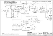
The Omnipressor has a single side chain with a bipolar control voltage. This is where the Blackmer VCA that's referenced to 0 db but can amplify or attenuate from there is key. What you get then is a single control that sweeps from compression to expansion. The rotation of the control then adjusts the ratio in either direction. And yes indeed it can whip up some crazy artifacts and wild behavior but that's the point. It's an artistic tool really. That said, the normal compression range is very nice. I prefer feedback compressors most of the time, but this feed-forward no doubt works well an was fun to use for a while.
Walter liked what this thing did to the bass guitar and it was used on many recordings. I'm pretty sure that it's on all of the bass on the "11 tracks of whack" album and at least some of Donald Fagen's Kamakiriad album. I don't know if he used it on any Steely Dan records. Looking back, I should have paid attention to the settings used. The late John Neff showed me and I should have taken pictures of the controls. Live and learn.
Here's the side chain less the RMS detector that's on the previous page.
Attachments
Last edited:
That's fairly easy to see in the schematic, with the op-amp arrangement around the control labeled "FUNCTION", which I assume is that single control.What you get then is a single control that sweeps from compression to expansion.
The envelope generator circuit is harder for me to follow. OK, signal comes out Q4 emitter, though D2, R19 - the attack control - and charges C9, buffered by U2. Simple enough. But then the release time seems to be gated by Q5 in the path of R20, such that only when input signal goes away, is "release" of the charge on C9 allowed. Why so elaborate?
What's the compression advantage of using that gating FET, versus say, a just a sink diode to Vref? The release control is 1M - much larger and of course I get why - versus 10K for the attack control. Is having say, a 500K across the cap while charging it though, say, 5K that bad? It'd be a bit of a voltage divider of course, but ??
I thought at first look Q5 was a constant current sink, so the cap discharges linearly, but now I see its a signal driven gate.
Then the DC envelope out from the U2 cap buffer feeds back to the transistor Q2, the other half of the - I assume - audio signal input LTP - and I just close the laptop screen at that point; completely lost now as to "How It Works". I could think of the gated release discharge, but that DC feedback has me well into "Bill Murray throwing golf club meme" territory.
Anyway - I'm particularly interested in the VCA control voltage deriving circuit. My latest attempt at one is fail; attack too slow, signal feeds through full blast before it get around to drive the VCA to attenuate. I'd be better off Fairchild style; a bridge rectifier, no attack resistor at all and 2uf // 200k.
The Omnipressor gates the release for two reasons. First it simply speeds up the attack time because the realease load on the timing capacitor C9 is completely removed during attack. The really interesting part however is that it allows slow attack while having fast release. The attack can be slower than the release and that's where some of the Omnipressor's crazy settings come from. I have seen some pro guitarists get interesting effects this way but I never worked with it long enough to get good at it. One of the things this does is allow volume swells that sound very volume pedal like.
And yes the Function control is a very simple sweep through the polarity and a cool trick really. The limit controls are also very useful as you can hold back the extremes and I found myself using them extensively to keep things under control.
And yes the Function control is a very simple sweep through the polarity and a cool trick really. The limit controls are also very useful as you can hold back the extremes and I found myself using them extensively to keep things under control.
This is my version of the timing circuits. It uses a single 20 Volt supply and that's why you see Vref and Vtc. Just treat these as the ground in a dual supply. In my circuit they come form reference generators. I'm reviewing all of this myself since I haven't seen it since 2021. It's interesting.
The dual 4.7 µF capacitors are SMD ceramics. There's two for component commonality. This could be a single 10 µF. I found 9.4 µF 5% to be just fine.
This also helps to clarify the original ciruit's use of a discrete op-amp and if I had finished this schematic and numbered the op-amps I could be more specific. Apparently I was in a hurry at the time to get on with the next project.
Last edited:
I'm working on a tube guitar amp and would like to incorporate compression into the design. I started out with "feed-forward", where I take the control envelope right off the incoming guitar signal, then apply it to Vactrols to turn down the output stage volume. It sorta worked.jjasniew, are you trying to build a feedback or feed-forward compressor?
Then after seeing the Fairchild schematic again, I tapped off an independent 70V output winding of the amplifier OPT, run through a full wave bridge, then a cap with a bleed resistor. I moved the Vactrols to the input stage of the amp (reason being the signal is so much less amplitude there) So now it's a feed-back. It sorta works too.
I havent yet got the effect amount dialed in using a panel control. The post volume of course now effects the amount of compression, whereas with the feed-forward only the guitar volume did that. Now when using a signal generator as input, I can crank up the post and watch the signals coming out the input tube diminish in amplitude, then come back up after I quickly close the post volume - in time with the RC time constant, so I know its "working". Unsure which way to go ultimately.
So the amplifier is a fully differential design, with the input tube doing phase split via a 12AX7 LTP arrangement using a current sink on the tubes cathodes. Everything is double from there through the output tubes; two sections of a 12AX7 as a "cold clipper", two 12BH7 driver triodes. Feedback from the OPT secondary is differential too, as I was lucky to get a 16 Ohm output tap.
The two Vactrols have their LED drivers in series and basically just stomp the output of the input phase splitter, after the decoupling caps, to ground. They are in basically parallel with the 250K "pre" volume control - a dual pot whose wipers go to the cold clipper stage.
When I removed the Vactrols from the output stage, I somehow reversed the signal phases so my feedback wasnt negative anymore. Squeel, squeel at full volume when before it was just fine. I thought for sure it had something to do with the Vactrols now being at the front of a very high gain circuit - and driven by that 70V winding. I moved circuits physically around in the chassis, grounded ends of floating circuits, shorted my unregulated (-) supply to ground for 20 minutes before finally figuring that one out and correcting it.
Ultimately, I'd like to get an effect similar to what the Rane does; just be louder longer by sustaining the H*** out of the guitar. I realize I could just buy a compressor and put that between the guitar and amp, but what fun is that?
I was going to say this, I've seen the same thing with the two high-value resistors to the gate for a FET attenuator in The Art of Electronics. I have a suspicion the Z2A voltage follower is overkill. It would be interesting to try the circuit with and without it to see how much difference there is.I stumbled upon the answer to my own Z2 A function question, found in one of Rod Elliott's excellent articles at https://sound-au.com/articles/vca-techniques.html
"A JFET used as a 'variable resistance' follows a square-law, and introduces a large second harmonic component - typically up to 25% THD with 50mV on the drain and at 6dB attenuation. To counteract this, it is essential that part of the signal on the drain is applied to the gate to cancel second harmonic distortion. The gate should have exactly half the signal that appears on the drain for optimum distortion cancellation."
So Z2 A was placed in that circuit for a very specific reason...
ETA: I read through Elliot's page and I can see where the buffer prevents control voltage feedthrough, among other things.
Last edited:
- Home
- Source & Line
- Analog Line Level
- The Omnipressor