Makes me wonder if this "square law" thing with FET attenuators is why the GE H11F Opto isnt used. There's no gate on the FET part, just drain and source. You'd have to go through the LED! Somehow...I was going to say this, I've seen the same thing with the two high-value resistors to the gate for a FET attenuator in The Art of Electronics.
I ran my simulation for the Rane limiter and it's interesting indeed. The Z2 buffer doesn't cancel signal distortion and it doesnt speed up the attack. It supresses control feed-through to reduce artifacts. Although this is not harmonic distortion in the signal path, it's distortion nonetheless and messes things up pretty badly at low frequencies. The rectifier being full wave means that it glitches twice per cycle and the phase changes with frequency so it's a nasty distortion.
The limiter in general is very crude compared to what I'm used to and it makes it interesting to analyze. I always like to see what the simplest version of things do and decide if they are good for anything. This thing I could see as a low end guitar limiter maybe, but I think that I'm already too spoiled. I'm guessing that Rane uses this because it's better than a clipping amplifier. In some cases it probably covers up not so frequent clipping pretty well. It is not however something you want acting on the usable signal. It's not what it's for.
I should add that the arguent against this limiter for clipping is that it's rather slow for that. It takes about a full cycle to act at 300 hz or so. That would let quite a bit of higher frequency clipping of an amplifier through.
It's also interestng that the FET is a whopping $32.00 at DigiKey. This is a growing problem. JFETS are disappearing and getting very costly. This is consistent with the many limitations that they have. There isn't really much use for them. I stopped using them altogether about 5 years ago.
The instruments amplifiers limiters are most often... well. Lol.
Rod Elliott have some interesting thoughts about them which match your conclusion Retrofier. The one used in his bass preamp project is interesting imho, it could fit well JJ's project i think ( Rod tested it with other instruments than bass, it use Vactrol,...).
Yes Jfets are getting pricey... seen outrageous price for 5457/59 recently! 😱
I'm still looking at this in simulation. It's pretty interesting and particularly where the relatively cheap J112 works better!
The idea however of canceling anything is pretty absurd because JFETS don't really do anything predictable. The curve is bent but the function that it obeys is not consistent between devices and not well defined in general. To put it simply they're crude. They don't have the mathematical magic of a BJT. It's a shame really because having a nice voltage controlled resistance would be great. These things just leave me looking for a better way.
That said, the guitar world tolerates less than perfect things and as long as J111, J112, and J113 stay reasonably available and cheap, well...
They do work reasonalbly well as audio switches and I have done that in the past. I have also seen them linearized with lots of feedback as guitar input buffers but the noise rains on that parade. And of course when used in op-amps they get linearized and the noise can be low enough for lots of applications. I guess this means that most of my use of JFETS is the TL072 and others. That's were they shine.
jjasniew, the H11F looks quite interesting. From what I can tell they are much more predictable and could be useful. I haven't seen this one. I used optocouplers in industry but never an FET output device. Cool! The down side is that the cheapest one I see is $3.38 for 1. It could be practical in some cases. It's certainly worth a look.
I bought a 10 from China off ebay for about $1 ea, shipped. Could you put enough current into the LED to get it to half range, put a resistor as an equal value resistor divider, put a signal in and measure the harmonic distortion of the ~ 0.5 attenuator? Unsure how the "square law" part of the FET output works; I figure it's "a resistor". Maybe not for AC, just DC...Cool! The down side is that the cheapest one I see is $3.38 for 1.
What's your preferred "precision rectifier" circuit, that feeds the attack / release circuity you've posted? I've been using this one;
I put just enough C across the R in the second op amp to minimize the ripple, trading off between that and "attack" speed. I'm up to 100k on the Rs, as I want to minimize the loading of the signal driving it. Better way? Or, if you use your attack / release generator following, you dont need any C at all?
Stumbled upon this today. I wonder what would happen if you put the GE H11F in place of the P channel FETs shown. Light the LED of the grounded gate one with enough current to drive it to minimum Rds, while the other provides current controlled variable gain via its LED.

https://www.electronicdesign.com/te...two-jfets-form-a-voltage-controlled-amplifier
https://www.electronicdesign.com/te...two-jfets-form-a-voltage-controlled-amplifier
This is the rectifier I'm using for my latest feedback compressor.
The transistors used here are often called "diode connected" but it's not true, they actually do have tranistor action and in some cases it matters but not here. You could just use 1N4148/914 etc.. Also the OPA168 and the 2N4401 are used as convenient simulation models but not what's in the actuall circuit. The transistors in reality are a dual surface mout device and the op-amps depend on the compressor application and supply voltage etc..
This one is designed to run from an LE80 regulator that can work from a 9 Volt battery very well. I have been doing low voltage circuit experiments in general that depend on rail to rail op-amps. What can be done with a single 8 Volt supply is surprising. I haven't done much with 5 Volt audio yet, but I may get around to that too.
The simulation power supply here is used to avoid drawing the reference generator etc. used in the actual circuit.
I was thinking AC to DC envelope generation could be sped up by using a graphic EQ and putting a converter after each band; obviously the higher frequencies would require less filter TC to get rid of any ripple and therefore could "attack" faster. I ran into this, which apparently does it in an 8 pin dip. The output is a multiplexed analog level. I suppose you could choose which bands effect the VCA at all, or make up some proprietary blend of which ones effect the VCA CV more. I'm losing grip on my OCD about this, so I better stop now and go play guitar in the sunshine I see out the window!

https://www.eetimes.com/msgeq7-based-diy-audio-spectrum-analyzer-for-badass-display/
https://www.eetimes.com/msgeq7-based-diy-audio-spectrum-analyzer-for-badass-display/
I looked of course, cant find anything about the Fluke chip that implements that circuit. What would you do for DIY? Put the transistors/resistors in a glass bottle and evacuate? Crazy people make their own vacuum tubes on YT...If you have a data sheet I would love to see it.
Feed forward. As part of a tube guitar amp I'm playing with. Found out the hard way; by the time the signal get through all the clipping, there's no dynamic left to pickup and turn into a CV. But at the first stage there still is. Hence, I get my envelope CV from there, use that to control a crude Vactrol based attenuator across the post volume. Seems to work best, I just need to make up a good controller for the Vactrol part. Hence my interest in these circuits.Are you working on a feedback or feed forward compressor?
I have other projects needing compression. One is a spin on Yamaha's Transacoustic where I put my voice through the guitar body as a reverb. Along with or instead of the guitar like Yamaha does. IMHO gives a very pleasant quiet evening "Corcovado" front porch solo performance experience, aside from having to wear a headset mic and deal with a cord. Could be 10X better with compression and an impulse EQ of whatever it is that the driver does, exciting a section of wood of the guitar back, FR wise.
Stumbled into that one after buying a Chinese "all in one" Transacoustic rip-off, complete with li-Ion battery to play with. They had a mic built into the box, as is late fashion to get some extra sound pickup from inside the guitar. I thought that was dumb, so I chopped out the mic and brought its signal input out to a 1/4" TRS. Then I can plug in my own mic, sing into it and the guitar body reverbs my vocal. Nice when it behaves. Unplugging the mic with the power on sends the reverb into IIR mode and I have to power cycle to get it to stop making noise.
Well that sounds like a nice fun and weird project. How interesting to use the gutar for reverb. I never did build a Vactrol based compressor but I do have a couple of Vactols here somewhere.
And regarding getting the evelope, this is a big deal when making a first class noise gate for guitars. You get the control signal just after the input buffer and that means the entire chain. In the case of pedal boards I have set guitarists up with an external input buffer with a control output. My noise gates using this two piece technique are quite impressive. The input buffer is the first thing the guitar sees, and then the gate part goes where you want it. They go right down to the resistive noise of a humbucker.
I have considered other reverb experiments but only ever did spring. I made two dual reverb units that used 4 spring and six spring tanks for some amazing sound. The drivers for the tanks were designed to give tube characteristics which warmed up the sound and gave a bit of compression to it. The signal to noise was over 100 db and I didn't even think that was possible for a spring. Making a super quite studio spring was my motivation at first but I didn't think that it would work so well. One of them is in a studio in the Seattle and the other is in a stidop in Sequim which is on the Olymic Peninsula.

I have one professional recording (Birch Piera and the Gin Joints) where the entire band goes through the dual spring and the guitarist is using one of my tweed combo amps that has the classic Accutronics surf spring in it. In all there's 3 tanks involved in the track and panned here and there. It's quite an effect. The dreamy smooth reverb is from a Type 9 tank with six springs, and the more surf sounding units are the classic Type 4 that Fender used.
And regarding getting the evelope, this is a big deal when making a first class noise gate for guitars. You get the control signal just after the input buffer and that means the entire chain. In the case of pedal boards I have set guitarists up with an external input buffer with a control output. My noise gates using this two piece technique are quite impressive. The input buffer is the first thing the guitar sees, and then the gate part goes where you want it. They go right down to the resistive noise of a humbucker.
I have considered other reverb experiments but only ever did spring. I made two dual reverb units that used 4 spring and six spring tanks for some amazing sound. The drivers for the tanks were designed to give tube characteristics which warmed up the sound and gave a bit of compression to it. The signal to noise was over 100 db and I didn't even think that was possible for a spring. Making a super quite studio spring was my motivation at first but I didn't think that it would work so well. One of them is in a studio in the Seattle and the other is in a stidop in Sequim which is on the Olymic Peninsula.
I have one professional recording (Birch Piera and the Gin Joints) where the entire band goes through the dual spring and the guitarist is using one of my tweed combo amps that has the classic Accutronics surf spring in it. In all there's 3 tanks involved in the track and panned here and there. It's quite an effect. The dreamy smooth reverb is from a Type 9 tank with six springs, and the more surf sounding units are the classic Type 4 that Fender used.
Attachments

The Dual Spring Reverb was all hand built with through hole parts. I don't do things like that anymore and it already seems like a past life. The case that looks sort of like a flight case is a DJ CD case.

The boards seen here mounted to the reverb tanks are the driver amplifiers. The one on the right shows how the power transistors use the reverb tank as a heat sink. The drive coils are 10 Ohm.

Anyway, that was my adventure with reverb. I hope to get back to it soon. I miss having high quality line level spring in the house.
The boards seen here mounted to the reverb tanks are the driver amplifiers. The one on the right shows how the power transistors use the reverb tank as a heat sink. The drive coils are 10 Ohm.
Anyway, that was my adventure with reverb. I hope to get back to it soon. I miss having high quality line level spring in the house.
OK, now you got me started. I found another cool example of two of my amps with spring reverb. Kate is singing through my analog tube emulating mic preamp going into a Type 9 spring. This is all in the amp on the right. The MCM amp on the left that the guitar is going through has a Type 8 Accutronics tank. I love that all of the sound on these recordings are going through my circuits and that includes reverb and EQ. Both amps have 3 band constant Q EQs.
Last edited:
OK, I forgot about the tremolo! This is in the MCM amp on the left and it's done by modulating the OTA VCA that's also designed to give tube effect. It's incredibly rich. He doesn't have a pedal board at all here. The guitar plugs into one amp and the volcal mic directly into the other.
I love how Jason cranks the reverb for his outtro. He's a real pro in so many ways.
I love how Jason cranks the reverb for his outtro. He's a real pro in so many ways.
Getting back to the Omnipressor, here's the original log amplifier/rectifier. It was "cookbooked" back in the day from various data sheets etc. as far as I can tell. I found various references to similar circuits. David Blackmer did recognize the problem of the complexety and came up with a much simpler version and Wayne Kirkwood further simplified that circuit and I adapted Wayne's version for my version of the Omnipressor.

This is the version that I used for my Omnipressor with great success and that was a bit of a surprise. It seems too good to be true that it could boil down that much but this has quite a bit to do with the transistors available today. Wayne used a rather costly THAT corporation transistor array and I used some surprisingly cheap and readily available dual transistors and it works great.
From the perspective of an Oscilloscope, this circuit is almost impossible to distinguish from that elaborate orignal Omnipressor version. It's even temperature stable using the devices that I did.

It's very interesting to note here that the Omnipressor did not filter the log amp to end up with an RMS output. It peak detects the log amp instead. This is an important component to the Omnipressors behavior.
This is the version that I used for my Omnipressor with great success and that was a bit of a surprise. It seems too good to be true that it could boil down that much but this has quite a bit to do with the transistors available today. Wayne used a rather costly THAT corporation transistor array and I used some surprisingly cheap and readily available dual transistors and it works great.
From the perspective of an Oscilloscope, this circuit is almost impossible to distinguish from that elaborate orignal Omnipressor version. It's even temperature stable using the devices that I did.
It's very interesting to note here that the Omnipressor did not filter the log amp to end up with an RMS output. It peak detects the log amp instead. This is an important component to the Omnipressors behavior.
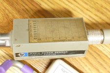
The Hewlett Packard RF power meters from the same time period used a similar bridge circuit with two tiny 50 ohm thermistors in place of the transistors. The bridge had a square wave signal in the 50 KHz range applied to the +V port and the RF signal capacitively coupled to one thermistor to heat it. The RF was limited to 50 MHz on the low end, but the upper end was well into the GHZ region. The opamp would not respond to the milliwatt level RF signals above 50 MHz. My mid 80's version goes to 18 GHz but the factory cal chart wore off long ago.If you really want to go out on the fringes of audio envelope generation; I wonder how fast you could make it go with SMD?
View attachment 1318965
In my quest to reinvent the VCA portion of the Fairchild compressor from post #6 with real 6386 tubes I discovered the reason for 4 parallel $100+ tubes. At low gains the tubes are biased to sub miliamp current levels. Here the Gm is near zero and the tubes can't drive the reactive load presented by the transformer at the frequency extremes. Fairchild didn't have mosfets, but I do, so I put a mosfet follower between the tube and the transformer so one 6386 could reach 40 KHz before rolling off. I then set out to find a $1 tube that did the same job. The triode wired pentode seen here can be any of the tubes originally designed for TV IF amp use. I built and tested the VCA with the 6EJ7 in mind, but it has "6KT6's" in it now since I have lots of them, all counterfeit. I have no clue what they really are. All of the 9 pin tubes with the same pinout worked with some variation in the control voltage needed for 60 to 70 dB of dynamic gain control range.
I have not tried it yet, but it would seem that an ordinary chip amp could be used to drive the rectifier circuit. Real 6386 tubes are varaible Mu and require tens of volts to get tens of dB of gain control range. Conventional triodes and triode wired pentodes work with less than 10 volts of control voltage range.
Attachments
- Home
- Source & Line
- Analog Line Level
- The Omnipressor