
Regulators to power oscillators and frequency doublers
The Well Regulated Power Supply
The Well Regulated Power Supply
20 VAC 30VA , this is the suggested transformer
https://www.mouser.it/ProductDetail/Bel-Signal-Transformer/DP-241-6-20?qs=0/2GmT7MRM%2BBr/5qnPZhcg==
The same transformer for the TWRPS-pp
https://www.mouser.it/ProductDetail/Bel-Signal-Transformer/DP-241-6-20?qs=0/2GmT7MRM%2BBr/5qnPZhcg==
The same transformer for the TWRPS-pp
The new Pierce oscillator
For those who got At-Cut crystals from the previous batches these are the phase noise plots of the new Pierce oscillators at 5.6448 MHz and 6.144 MHz.
Considering that they are fundamental AT-Cut crystal the phase noise performance are very good, -134 dBc and -140 dBc at 10 Hz from the carrier, they perform better than an OCXO I have bought a few years ago from a professional manufacturer.
Attachments
I forgot, obviously AT-Cut crystals are available in the new GB according to the MOQ like the SC-Cut type.
The new TWTMC-PXO Pierce oscillator is a less expensive alternative to the top line oscillators (TWTMC-DXO and TWTMC-EXO), although it achieves very good phase noise performance as well.
The new TWTMC-PXO Pierce oscillator is a less expensive alternative to the top line oscillators (TWTMC-DXO and TWTMC-EXO), although it achieves very good phase noise performance as well.
For those who got At-Cut crystals from the previous batches these are the phase noise plots of the new Pierce oscillators at 5.6448 MHz and 6.144 MHz.
Considering that they are fundamental AT-Cut crystal the phase noise performance are very good, -134 dBc and -140 dBc at 10 Hz from the carrier, they perform better than an OCXO I have bought a few years ago from a professional manufacturer.
I understood that lower crystal frequency brings lower phase noise. Why is the phase noise of the 6mhz in these plots than the lowest?
5.6448 MHz and 6.144 MHz are very close in frequency, so one expect similar phase noise. Moreover the circuit is exactly the same.
So the difference comes from the crystals, the 6 MHz crystal is better than the 5 MHz one.
Difficult to say why, maybe a slightly different cut process, or a little difference in polishing.
I will ask Laptech.
So the difference comes from the crystals, the 6 MHz crystal is better than the 5 MHz one.
Difficult to say why, maybe a slightly different cut process, or a little difference in polishing.
I will ask Laptech.
Frequency doublers: 11 to 22 MHz (one doubler) and 5 to 22 MHz (series of 2)
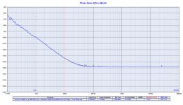
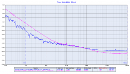
I attach the phase noise measurements of the other doublers.
The first plot is the comparison between the Driscoll with crystal at 22.5792 MHz (pink line) against the same Driscoll circuit with crystal at 11.2896 MHz followed by the frequency multiplier (blue line).
The close in phase noise of the oscillator followed by the doubler is 10 to 12 dB better than the single oscillator at the same frequency.
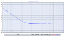
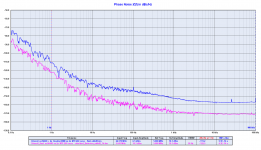
The second plot is the comparison between the Driscoll at 11.2896 MHz (pink line) against the same oscillator followed by the frequency multiplier to get 22.5792 MHz (blue line).
The close in phase noise is almost identical, better then the expected theory.
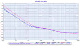
The third plot is the comparison between the Driscoll with crystal at 22.5792 MHz (pink line) against the same Driscoll circuit with crystal at 5.6448 MHz followed by 2 frequency multipliers (blue line).
The close in phase noise of the oscillator followed by the doubler is 10 to 20 dB better than the single oscillator at the same frequency.
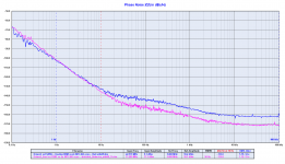
The fourth plot is the comparison between the Driscoll at 5.6448 MHz (pink line) against the same oscillator followed by a pair of frequency multipliers to get 22.5792 MHz (blue line).
The theory is confirmed, around 12 dB difference (6dB for each multiplication).
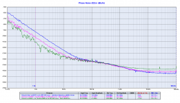
The last plot is the comparison between the Driscoll with crystal at 22.2792 MHz (blue line) against the same Driscoll circuit with crystal at 11.2896 MHz followed by the frequency multiplier (pink line) against the Driscoll with crystal at 5.6448 MHz followed by a pair of frequency multipliers.
The 5.6448 MHz oscillator followed by the series of two frequency multipliers performs the best, although the 11.2896 MHz oscillator followed by a single doubler has a very good close in phase noise.
The plot also confirms the theoretically 6 dB of close in phase noise increasing for each frequency duplication.
There are two more frequency multiplier: 22.5792 to 45.1584 MHz and 45.1584 to 90.3168 MHz (and also all the x48 family frequency doublers) but we cannot measure them because the Timepod is limited to 30 MHz.
BTW, you can apply the theory to calculate the phase noise of the high frequency doublers, 6 dB for each duplication.
Let me remember the the series of frequency doublers should not exceed 2 because we loose 3 dBm for each duplication.
I attach the phase noise measurements of the other doublers.
The first plot is the comparison between the Driscoll with crystal at 22.5792 MHz (pink line) against the same Driscoll circuit with crystal at 11.2896 MHz followed by the frequency multiplier (blue line).
The close in phase noise of the oscillator followed by the doubler is 10 to 12 dB better than the single oscillator at the same frequency.
The second plot is the comparison between the Driscoll at 11.2896 MHz (pink line) against the same oscillator followed by the frequency multiplier to get 22.5792 MHz (blue line).
The close in phase noise is almost identical, better then the expected theory.
The third plot is the comparison between the Driscoll with crystal at 22.5792 MHz (pink line) against the same Driscoll circuit with crystal at 5.6448 MHz followed by 2 frequency multipliers (blue line).
The close in phase noise of the oscillator followed by the doubler is 10 to 20 dB better than the single oscillator at the same frequency.
The fourth plot is the comparison between the Driscoll at 5.6448 MHz (pink line) against the same oscillator followed by a pair of frequency multipliers to get 22.5792 MHz (blue line).
The theory is confirmed, around 12 dB difference (6dB for each multiplication).
The last plot is the comparison between the Driscoll with crystal at 22.2792 MHz (blue line) against the same Driscoll circuit with crystal at 11.2896 MHz followed by the frequency multiplier (pink line) against the Driscoll with crystal at 5.6448 MHz followed by a pair of frequency multipliers.
The 5.6448 MHz oscillator followed by the series of two frequency multipliers performs the best, although the 11.2896 MHz oscillator followed by a single doubler has a very good close in phase noise.
The plot also confirms the theoretically 6 dB of close in phase noise increasing for each frequency duplication.
There are two more frequency multiplier: 22.5792 to 45.1584 MHz and 45.1584 to 90.3168 MHz (and also all the x48 family frequency doublers) but we cannot measure them because the Timepod is limited to 30 MHz.
BTW, you can apply the theory to calculate the phase noise of the high frequency doublers, 6 dB for each duplication.
Let me remember the the series of frequency doublers should not exceed 2 because we loose 3 dBm for each duplication.
Attachments
-
 Driscoll_225792 vs Driscoll_112896_Doubler.png151.4 KB · Views: 498
 -
 Driscoll_112896 vs Driscoll_112896_Doubler.png154.8 KB · Views: 482
 -
 Driscoll_225792 vs Driscoll_56448_2XDoubler.png152.3 KB · Views: 486
 -
 Driscoll_56448 vs Driscoll_56448_2XDoubler.png161.1 KB · Views: 306
 -
 Driscoll_225792 vs Driscoll_112896_Doubler vs Driscoll_56448_2XDoubler.png171.2 KB · Views: 331
The 5/6 SC cut and the new driscoll/ doubler look promising. Recently, my early 24 sc-cut Driscoll start to drift unexpectedly. Sometimes it will start at 26.6Mhz. I suspect the heat from the oven changed some of the components over time. Need to replace the parts again.
No, it jumps from C-mode to the B-mode resonance of the SC-cut crystal
which is 10% higher. You need a circuit that is more selective.
(Selectivity that is not in the crystal.) The B-mode resonance can easily
have the same or even better Q, but the TC is ridiculous.
Cheers, Gerhard
which is 10% higher. You need a circuit that is more selective.
(Selectivity that is not in the crystal.) The B-mode resonance can easily
have the same or even better Q, but the TC is ridiculous.
Cheers, Gerhard
Last edited:
I attach the phase noise measurements of the other doublers.
The first plot is the comparison between the Driscoll with crystal at 22.5792 MHz (pink line) against the same Driscoll circuit with crystal at 11.2896 MHz followed by the frequency multiplier (blue line).
The close in phase noise of the oscillator followed by the doubler is 10 to 12 dB better than the single oscillator at the same frequency.
The second plot is the comparison between the Driscoll at 11.2896 MHz (pink line) against the same oscillator followed by the frequency multiplier to get 22.5792 MHz (blue line).
The close in phase noise is almost identical, better then the expected theory.
The third plot is the comparison between the Driscoll with crystal at 22.5792 MHz (pink line) against the same Driscoll circuit with crystal at 5.6448 MHz followed by 2 frequency multipliers (blue line).
The close in phase noise of the oscillator followed by the doubler is 10 to 20 dB better than the single oscillator at the same frequency.
The fourth plot is the comparison between the Driscoll at 5.6448 MHz (pink line) against the same oscillator followed by a pair of frequency multipliers to get 22.5792 MHz (blue line).
The theory is confirmed, around 12 dB difference (6dB for each multiplication).
The last plot is the comparison between the Driscoll with crystal at 22.2792 MHz (blue line) against the same Driscoll circuit with crystal at 11.2896 MHz followed by the frequency multiplier (pink line) against the Driscoll with crystal at 5.6448 MHz followed by a pair of frequency multipliers.
The 5.6448 MHz oscillator followed by the series of two frequency multipliers performs the best, although the 11.2896 MHz oscillator followed by a single doubler has a very good close in phase noise.
The plot also confirms the theoretically 6 dB of close in phase noise increasing for each frequency duplication.
There are two more frequency multiplier: 22.5792 to 45.1584 MHz and 45.1584 to 90.3168 MHz (and also all the x48 family frequency doublers) but we cannot measure them because the Timepod is limited to 30 MHz.
BTW, you can apply the theory to calculate the phase noise of the high frequency doublers, 6 dB for each duplication.
Let me remember the the series of frequency doublers should not exceed 2 because we loose 3 dBm for each duplication.
Hi, Andrea,
Congradulations on the fantastic results and thanks for sharing and everything. This really changes the perspective of group buy. I suppose a 5.6448mHz SC cut would be most sort after. I am in for one.
Also, I am thinking to get a 24mHz AT cut for an FPGA project, with simply Pierce or your New Pierce circuit. I suppose it would be wiser to go 24mHZ directly, instead of 6mHZ pierce followed by two doublers? Not sure if there are other interested forumer to meet the MPQ though.
Cheers.
W. YAN
A question..
The Timepod still has Wilkinson power splitters, am I right? Did not try to change that?
Just asking because of the very high quality of these tests, ('complimenti'). Scraping the bottom of the barrel, so it could become a factor?
I would not know what to replace them with. A resistive divider would not be better.
When you approach the thermal noise at < 170 dBm, the noise of the 200 Ohm
resistor in the Wilkinson starts to play a role unless it's deep frozen. That would not be
a show stopper by itself, but the noise of this resistor is in anti-phase at the two
outputs, so it cannot be correlated away. That can even lead to unphysical results
if it happens to cancel "normal" noise.
in #2468, I have given a pointer to the "How Low Can They Go" article by
Rohde, Poddar e.a. that sheds some light on that.
Last edited:
- Status
- Not open for further replies.
- Home
- Source & Line
- Digital Line Level
- The Well Tempered Master Clock - Building a low phase noise/jitter crystal oscillator