It would be a big help for the ones who can solder themselves if you can make a standard parts list at mouser.
This will make it easy to purchase all the needed parts (it will persuade me to buy the bare boards instead of the finished ones)
I has cost me quite some time to order all the parts for the previous driscoll boards out of the supplied parts lists, there were also some parts not available and that makes it hard to find an alternative if you are not sure what the important component features are.
A parts list with all combinations can be made on mouser website and easily shared. For the specific frequency dependent parts a note can be added so the buyer can delete all unneeded parts.
Please take this into consideration.
Regards,
As soon as all the boards are ready I will create the shared BOM for each device on Mouser (bare board and semi finished).
Is it possible to ask a couple more questions about the DAC or better to wait till you formally announce it?
Please, let me know your questions.
Frequency doubler
The frequency doubler is almost ready, I attach the first measurements.
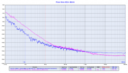
The first plot is the comparison between the Driscoll with crystal at 11.2896 MHz (pink line) against the same Driscoll circuit with crystal at 5.6448 MHz followed by the frequency multiplier (blue line).
The close in phase noise of the oscillator followed by the doubler is far better than just the oscillator at the required frequency.
Only a higher nois floor due to the frequency multiplication.
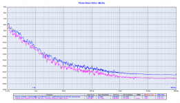
The second plot is the comparison between the Driscoll at 5.6448 MHz (pink line) against the same oscillator followed by the frequency multiplier to get 11.2896 MHz (blue line).
One more time the real world confirm the theory: each time you multiply the frequency the phase noise increases by 6 dB. Even the 1/f 3 phase noise is better than the assumed theory.
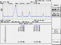
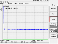
The third and fourth pictures are the noise spectrum of the duplicated clock.
The harmonics are very low and there are no spurious up to 1 GHz.
The frequency doubler is almost ready, I attach the first measurements.
The first plot is the comparison between the Driscoll with crystal at 11.2896 MHz (pink line) against the same Driscoll circuit with crystal at 5.6448 MHz followed by the frequency multiplier (blue line).
The close in phase noise of the oscillator followed by the doubler is far better than just the oscillator at the required frequency.
Only a higher nois floor due to the frequency multiplication.
The second plot is the comparison between the Driscoll at 5.6448 MHz (pink line) against the same oscillator followed by the frequency multiplier to get 11.2896 MHz (blue line).
One more time the real world confirm the theory: each time you multiply the frequency the phase noise increases by 6 dB. Even the 1/f 3 phase noise is better than the assumed theory.
The third and fourth pictures are the noise spectrum of the duplicated clock.
The harmonics are very low and there are no spurious up to 1 GHz.
Attachments
.....
One more time the real world confirm the theory: each time you multiply the frequency the phase noise increases by 6 dB.
...
Thank you very much for providing all that information, great job
")
Could you please help me understanding that number (in bold) by putting it into some context ? (Is it big enough to be important ? ...
)
Last edited:
Suppose you have a signal source at 10 MHz and you have connected
a FM/PM demodulator to its output. That could be a ratio detector in
principle, just like in an ordinary FM receiver.
Say, you get an detector output of y volts for a modulation of x.
Then you get twice the volts for twice the modulation.
Twice the voltage is 4 times the power or 6 dB more.
If you double the frequency from 10 to 20 MHz, you also double
the modulation in Hz or degrees, so the 6 dB apply.
dBs are power ratios. They are calculated as 10*log10(power1/power2).
For power1/power2 = 4 that results in 6.0206 dB.
In history, they first used the Bel. (after Graham? Bell, the phone guy)
That proved to be too big to be practical. So they moved on to deci-Bel,
that's where the 10*.... comes from.
Last edited:
Thank you very much for providing all that information, great job
Could you please help me understanding that number (in bold) by putting it into some context ? (Is it big enough to be important ? ...
Theoretically every time you multiply the frequency you should get a phase noise around 6 dB worse than the basic oscillator and the phase noise plot of the doubler confirms the theory.
This allows to get better performance using the basic oscillator at lower frequency and then multiply it one or more times to achieve the required frequency.
For example, looking at the above plots, if you need 11.2896 MHz you get better phase noise performance multiplying the basic oscillator at 5.6448 MZ by 2 times rather than just using the oscillator at 11.2896 MHz.
However there is a limit to duplication because you loose around 3 dBm output for each multiplication.
The suggested limit is 2 times, so if you need 45.1584 MHz you should start from 11.2896 MHz and multiply by 4 (two cascade doubler).
Well explained by Gerhard in post #2607, thanks Gerhard.
Last edited:
The frequency doubler is almost ready, I attach the first measurements.
The first plot is the comparison between the Driscoll with crystal at 11.2896 MHz (pink line) against the same Driscoll circuit with crystal at 5.6448 MHz followed by the frequency multiplier (blue line).
The close in phase noise of the oscillator followed by the doubler is far better than just the oscillator at the required frequency.
Only a higher nois floor due to the frequency multiplication.
The second plot is the comparison between the Driscoll at 5.6448 MHz (pink line) against the same oscillator followed by the frequency multiplier to get 11.2896 MHz (blue line).
One more time the real world confirm the theory: each time you multiply the frequency the phase noise increases by 6 dB. Even the 1/f 3 phase noise is better than the assumed theory.
The third and fourth pictures are the noise spectrum of the duplicated clock.
The harmonics are very low and there are no spurious up to 1 GHz.
Beautiful, so this demostrate that worth to duplicate (or 4x and so on..) the very low phase noise lower frequency crystal like using the requested frequency at directly.
@gerhard thank you for the example, super illustrative !! . love it
I am familiar with dBs on other fields ... like if you change the level up 6dB in
- loudness perception .. you get a loudness gain factor of 1.516
- sound pressure effect ... you get a voltage gain factor of 2
- sound intensity ... you get a power gain factor of 4
So in my mind I see that (i.e) if I wanted to double the sound pressure of my speakers then I would need to multiply by a factor of 4 the power of my amplifier. In both cases we are talking about going up 6dB, but referenced to a different dimension (and the calculation is also different ... ). Hope that at least that is correct.
@andrea_mori : thank you andrea, greatly appreciated
I can see that having the base oscillator plus the multiplier has better noise spectrum than the correspondent higher frequency oscillator. What I am trying to sense is a feel for how much of a difference is that. You say 6dB and that is ok. I guess I do not see well in which context those 6dB make an impact and where. Maybe this question is offtopic, if that is the case I apologise in advance
thank you guys for addressing my questions
Rather than the 6 dB difference between the base oscillator and the multiplied one you should look at the phase noise difference between the multiplied oscillator and the the one directly at the required frequency (the first plot).
The oscillator folllowed by the doubler has far better close in phase noise (10 to 20 dB), that's what we are looking in digital to analog conversion.
The oscillator folllowed by the doubler has far better close in phase noise (10 to 20 dB), that's what we are looking in digital to analog conversion.
As soon as all the boards are ready I will create the shared BOM for each device on Mouser (bare board and semi finished).
That’s excellent thank you!
Please, let me know your questions.
I was most curious about how the output will be handled, for example if an I/V stage would be used or if it would be voltage output like the soekris DACs.
Next days I will publish the phase noise plot of the oscillator at 5.6448 MHz followed by two multipliers.
Unfortunately we cannot measure the phase noise of the frequency multipliers to 45/49 and 90/98 MHz because the Timepod upper frequency limit is 30 MHz.
BTW, if the multiplier to 22 MHz confirms the 6 dB added to the base oscillator we can assume this behaviour as a rule.
Unfortunately we cannot measure the phase noise of the frequency multipliers to 45/49 and 90/98 MHz because the Timepod upper frequency limit is 30 MHz.
BTW, if the multiplier to 22 MHz confirms the 6 dB added to the base oscillator we can assume this behaviour as a rule.
Last edited:
Could be cool to measure with the same tools and methos the former AT-Cut 5&6 Mhz side to side the SC-Cut of the same frequency And also the old Pierce with AT-Cut vs the New ENtry Level Pierce all in one with the 2 AT-Cuts 22/24 Mhz boards in order to make decision easier for the ones having cumulated the crystals and the boards of the previous group buys as the new people wanting to make a decision on an economy basis ?
Andrea, when do you open the payment/shipment phase please ? Are there some MOQs not reached yet ? (Maybe th BOM lists first ?)
A question to others designers ; what minimum frequency cristals would you chooe for a 20 bits dac chip AD1862 for a 24/192 max : slighty off topic , I apologise but as it is about to pick into the cristals/boards list of TWTMC stuffs It's a little related.
Many thanks
And also the old Pierce with AT-Cut vs the New ENtry Level Pierce all in one with the 2 AT-Cuts 22/24 Mhz boards in order to make decision easier for the ones having cumulated the crystals and the boards of the previous group buys as the new people wanting to make a decision on an economy basis ?Andrea, when do you open the payment/shipment phase please ? Are there some MOQs not reached yet ? (Maybe th BOM lists first ?)
A question to others designers ; what minimum frequency cristals would you chooe for a 20 bits dac chip AD1862 for a 24/192 max : slighty off topic , I apologise but as it is about to pick into the cristals/boards list of TWTMC stuffs It's a little related.
Many thanks
The new Driscoll and Differential oscillators don't work with the AT-Cut crystals because their ESR is too small.
If you meant the old oscillators I cannot measure them because I have no assembled boards to test, I'm sorry.
The new pico gate entry level Pierce oscillator will be measured, but don't expect great phase noise performance because it use a cheap crystal.
We are still testing some devices, I will publish order form and BOM as soon as we have ended tests and measurements.
Our new FIFO drives the AD1862 at 176/192 kHz with 5/6 MHz master clock in stopped clock mode.
- Status
- Not open for further replies.
- Home
- Source & Line
- Digital Line Level
- The Well Tempered Master Clock - Building a low phase noise/jitter crystal oscillator