I will try soon with 100R too.
So in the late evening I went back to my workroom, I switch the board several time again, and now it starts on 6V always.
Today morning it works like night, so I connect the freq doubler to the Drixo board.
The doubler works fine, freq is ok. After this I connect the second doubler, and its works too well, the freq is 4 times of basic freq.
If I load Drixo output with doubler, the voltage drops to 3Vpp on Drixo output.
After the first doubler its drops to about 2Vpp.
And after the second doubler it drops to about 800mV. Will it enough to drive STS board?
Each frequency doubler decreases the output level by 6 dBm, although your output after the second doubler looks a little low.
The STS board should work correctly, please connect it to the second doubler and check the square wave at the output of the STS.
Nice base line overview. I'll be interested to hear your thoughts on 2 next steps. 1. In your ultimate system with the fancy power supplies and TVC attenuators. Does the difference scale linearly, or with a more resolved system are there nuances in the ultimate clock that further differentiate it?, and
2. a comparison of the LM317 vs low noise ultimate PS again in your best system. I played around with this in the earlier WTMC at 45mHz and concluded that they are not as sensitive to PS as say your DAC might be. I did not take the time to compare this time. It was so simple to use a LM317 as a pre reg followed by choke filters and fancy reg that I just jumped to that and said likely good enough. I was just using parts left from other projects so there was really no reason to hold back.
Then it would be very interesting to see this vs battery. That might save people a lot of time and $ if it is negligible in impact. Your more methodical approach will give some useful guidance to those that follow.
Last edited:
So in the end, Sunday I try the 6 Mhz clock, I didnt change to 100R the crystal because the clock started well, with full amplitude, I switched it for several times, it was running well (dont know what was bad in saturday tests). It was runnig about 10 hours on Sunday, not stops.
So I connect today to the fifo reclock, both frequency is good, the music sounds well, very big space for first.
So I noticed a little ground loop in sound what wasnt before. The clock's Hammond house touched the metal chassis, maybe this causes, I will try to isolate.
So I connect today to the fifo reclock, both frequency is good, the music sounds well, very big space for first.
So I noticed a little ground loop in sound what wasnt before. The clock's Hammond house touched the metal chassis, maybe this causes, I will try to isolate.
For those using the Hammond boxes, better RF shielding is possible by not using the plastic end pieces. One could also not drill out a hole for the LED. Lastly wrap the plastic power connector in some grounded copper foil. I don't know how much any of this matters but it couldn't hurt.
Hello,
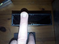
Happily i see my idea supported. A few days ago i posted a picture of the rectangular extruded aluminium i will use for my Italian clocks. It is one piece which will screen better. Of course will close one side of the tube airtight.
Will it matter how much space there is between the circuit and the rectangle.?
Of course the other side is a bit difficult to screen with all the connectors.
Maybe sliding the circuit deeper inside and close the rectangle with aluminium with a few tiny holes just big enough to pass the cable and not the connectors. So make the connections and then close the boxes..
Greetings,Eduard
Attachments
gabor80
FWIW, as I chased ground loop I tried grounding the SMA output. My sense was it was bad for sound. So if your Hamond case touches grounded other case then you may have similar sound degradation. I look forward to you findings as you experiment with your system.
What is your experience, what you you mean "bad for sound"? The space or clarity etc.?
For those using the Hammond boxes, better RF shielding is possible by not using the plastic end pieces. One could also not drill out a hole for the LED. Lastly wrap the plastic power connector in some grounded copper foil. I don't know how much any of this matters but it couldn't hurt.
... Another option is to use the "carbon foam" that is often used to place ICs on. It is my experience that it works sort of like an "absorber/diffusor" that absorbs - and possibly diffuses - the EMR inside the cabinet/box. It can be quite audible with DACs depending on the EMR level inside the cabinet.
I would tape it to the cabinet with double adhesive tape (small strips so that the foam may connect with the cabinet metal) or small areas of e.g. silicone rubber.
I would also place something (paper or the like) at the "inside" side of the foam so that the foam doesn't "dust" onto the circuitry over time.
Cheers,
Jesper
So I write a short experience report.")
I got an 5 Mhz Drixo, its direct connected to STS board, and to FIFO II and its clock board. The other Drixo is 6Mhz it made 4 times to 24 Mhz and its connect to STS and Clock board. (I listen to usually 44, 96 and 192 KHz samle freq tracks)
The improvement is hearable for first hearing, the low and high frequencies are more precise, highs less harsh, all more musical.
Biggest improvement is the space and the details, fantastic.
I listen to several tracks at all sample frequency, I never heard this tracks so very detailed, lots of new details become to hear, the intruments more separate, and the echoes more cleaner. I discovered new instruments at certain tracks, so I say it is worth the price.
The 44khz tracks a littlle more precise and strong bass than 96-192 Khz, I think the 5 Mhz clock is very-very good close-in PN, best Redbook experience to this date.
Thanks for sharing your experience with the sound with the new clocks. Very consistent with what I hear.What is your experience, what you you mean "bad for sound"? The space or clarity etc.?
The brief experience with "bad" sound was a surprise shrinking of sound stage. Normal sound stage is deep and wide. Listening to well recorded track it extends well beyond the speakers and sits far behind the plane of the speakers. The "bad" was all of a sudden the sound stage was more like the orchestra is miniature one sitting on a table between the speakers. Not a subtle change at all. It seemed to result when I grounded the shield of the clock coax. Back to normal when ground removed.
Important to note that I am experiencing some issues with what I think are U.FL cables that need to be replaced. So it is possible that my observations are not reliable. I have new cables ordered and have just put everything on hold for now.
Hello,
SO the way the clocks and the associated circuitry are '' housed '' is a key element in the final result.
I found a 50 mm thick pressed cork panel that i will use to make a kind of sound proof box to isolate the 6 aluminium rectangles.
My intention is to put the supercap in the attachment in between the two trinities and give each unit its own connection to the supercap terminal. SO there will be just one power cable entering the soundproof box. I think giving each unit a cable coming from the outside will/could introduce more vibrations from outside.
In between the 6 rectangles the cork does not have to be as thick.
Of course the boards are '' interconnected '' by the rather rigid coaxial cable. If the circuit is kind of fixed to the frontpanel by the terminal for this cable lots of vibration reducing elements are kind of abolished.
So i think the best idea to wrap all the boards in( carbon foam/ natural fiber????), makes the coaxial connections and slide the boards inside the tube.
If you slide them deeper into the rectangle will the opening on the front have less influence. Of course it will be easy to cover the opening and just leave an opening for the DC supply and the coaxial cables.
I am sure some of these things can be ''determined '' by specific knowledge, most could be measured.
The aluminium tubes were thrown away at work . So invest 25 euro on cork and glue, maybe some lead sheet( sound isolation) to cover the aluminium . Even if it ads up to 75 Euro if it gives an improvement it is still cheap compared to the total clock ''arrangement''
Greetings, Eduard
Attachments

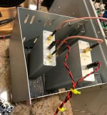
I noticed a SQ problem when I added a doubler. Where I live I need strong RFI attenuation. What always works best here is steel shielding. The SQ problem with the doubler in circuit was fixed by the shielding as shown below. To get the equivalent shielding from aluminum takes about 1/2" thick walls.
Attachments
Last edited:
Nice. That will stop a lot of the stuff around most houses.
My company produced RF comms gear for the utility industry. As many here will know, the lower the frequency, the better the penetration. 5.8g will bounce off anything. 2.4g and 900mHz will easily penetrate some pretty substantial metal boxes. 400mHz will go for miles through almost anything. I can only imagine how far 5mHz would travel. The good news is it needs a very long antenna.
My company produced RF comms gear for the utility industry. As many here will know, the lower the frequency, the better the penetration. 5.8g will bounce off anything. 2.4g and 900mHz will easily penetrate some pretty substantial metal boxes. 400mHz will go for miles through almost anything. I can only imagine how far 5mHz would travel. The good news is it needs a very long antenna.
"...900mHz will easily penetrate some pretty substantial metal boxes."
No kidding, maybe good for messaging deep submarines but the data bandwidth at 900 milli-Hertz would be almost useless. Unless, that was supposed to be 900MHz
EDIT: More seriously, for some reason I don't fully understand, seeing mHz used instead of MHz always makes me feel like it could be confusing to some people.
Last edited:
Hello,
So we will need to give the six circuits each its own metal housing which is easy to do with the help of Mouser.
The clock was considered the most sensitive part so people start giving possible solutions. Now the doublers are also to be taken care of even if already placed in their own alumium? enclosure.
I think Andrea should give some guidance ! If steel ( the one that is magnetic) works well why MUCH more expensive material like aluminium and copper are used?
@Markw4 Could it be possible you pick up RF because of long ? power cables.
Could turning the location of the doublers 90 degrees make things different.
Again Andrea should add a little more information here or in the manual. It would be weird to spend this much money compared to an already considered audiophile clock and achieve only a minor improvement because you didnt do it the way it should be done to create an improvement in every room.
Greetings, Eduard
Last edited:
EDIT: More seriously, for some reason I don't fully understand, seeing mHz used instead of MHz always makes me feel like it could be confusing to some people.
Not the first time you have had to correct me on this one
I seem to have Mega dyslexia wrt mHz vs MHz- Status
- Not open for further replies.
- Home
- Source & Line
- Digital Line Level
- The Well Tempered Master Clock - Building a low phase noise/jitter crystal oscillator