Many variations on the Pierce oscillator, usually with a single transistor or a differential pair as the undamping amplifier and with an amplitude control loop around it.
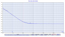
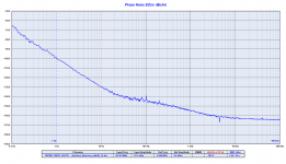
Strange, we have got good result even with a Pierce and AT-Cut crystal, this is a Pierce at 6.144MHz
Attachments
Possibly air currents,, Xtal quality, I don't know enough about your oscillator to comment.
Again, I don't doubt it is good. I do wonder how good is good enough. If you are improving something, you want a baseline to compare to. You have not done that.
The music tests are merely an opinion and basically useless as proof of anything. Yes, I read the darned evaluations. You needed to correlate some measurements to actual tests to show reduced defects in the sound. Music is pretty useless for that purpose. It is good to make others feel good I guess, but falls far short of anything concrete that you should use to sell your oscillator.
I don't see you ever making measurements to see what the average oscillators performance is, or what makes a difference. You will leave that to others I guess. So I will devote my time to something that is worthwhile. Believe it or not, I was trying to help you. The information I was asking of you would have been useful to you and others. You just don't see it.
-Chris
Again, I don't doubt it is good. I do wonder how good is good enough.
-Chris
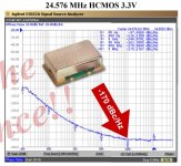
30dB better than the Crystek CCHD-957 at 10 Hz from the carrier?
Attachments
I don't see you ever making measurements to see what the average oscillators performance is, or what makes a difference. You will leave that to others I guess. So I will devote my time to something that is worthwhile.
-Chris
Thanks Chris - Glad to see some finality here.
I'm sure I will see you around on other threads. In the meantime the community can get back to subjective and objective measurements and testing.
Good luck in your ventures.
@syn08: Joseph is working on that, and you are still mixing up bandwidths.
Sorry Marcel, I don't. I have to admit I have no idea what you are talking about here, and I am pretty sure you don't understand my point of view as well.
The process gain of a FFT is defined as 10log(N/2) where N is the number of lines in the FFT (here, N=8,000,000 something) which is 66dB process gain. Now, add this process gain to the FFT noise floor and one gets the SNR of the ADC.
You may want to review this reference https://www.analog.com/media/en/training-seminars/tutorials/MT-001.pdf pp. 7.
Next time when trying to engage, please stop using one line dismissals and try to explain yourself (or provide a reference if you don't have the time). I know we collided several times in the past on different topics, if you hold any grudges that's your problem, not mine.
Last edited:
Hi lasercut,
That is what happens when the experiment hasn't been well designed. As he stated, it was a quick test and did not apply to this oscillator or situation. It was a proof of concept more than anything.
I'm not going to train you. That takes time, text books (or PDFs) and my training cost thousands. But the resources are out there for you to do it for free. Some info is right here. Knock yourself out!
-Chris
I think I understood enough then... it does prove what is relevant, measured improvements are possible from improved clocking, even against one of the best measuring DACs on the market currently.
Not like it will be a surprise if a controlled version of the test shows similar improvements.
I think I understood enough then... it does prove what is relevant, measured improvements are possible from improved clocking, even against one of the best measuring DACs on the market currently.
.
Except it doesn't. It just shows one DAC is better than another at that objective parameter. Correlation is not causality. Could be anything or dozens of things as everything gets critical as you chase the last few dB.
Except it doesn't. It just shows one DAC is better than another at that objective parameter. Correlation is not causality. Could be anything or dozens of things as everything gets critical as you chase the last few dB.
It could be anything and everything, but all related to clocking if we are looking at the effects on jitter... no?
Syn08, I think it's simple. Marcel had been talking of noise spectral density normalized to 1Hz, and You are talking about process gain (the integrated total in full nyquist bandwith). The difference between the two is the full bandwith integration. Your number is higher
Syn08, I think it's simple. Marcel had been talking of noise spectral density normalized to 1Hz, and You are talking about process gain (the integrated total in full nyquist bandwith). The difference between the two is the full bandwith integration. Your number is higher
Maybe, but then I don't understand the dismissive comment in https://www.diyaudio.com/forums/dig...itter-crystal-oscillator-438.html#post6711058 when it was obvious the process gain is wrong.
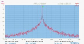
I have re-done partially the test. Was interested to see the skirt of D90 at 10kHz. It stays basically the same.
It should theoretically go significantly down. So it's not the result of the down conversion dividing the frequency deviation.
For me, it seems, correlates like as described by John here:The Well Tempered Master Clock - Building a low phase noise/jitter crystal oscillator
It should theoretically go significantly down. So it's not the result of the down conversion dividing the frequency deviation.
Up, I think, as the ratio from the clock to the output frequency gets smaller. Anyway, it's clear there is something else going on, something that's audio frequency independent.
The signal power is actually -4.091 dB on Joseph's plots from post #4311, so the discrepancy is 4.091 dB worse than I wrote earlier. That doesn't change anything, of course.
Maybe, but then I don't understand the dismissive comment in https://www.diyaudio.com/forums/dig...itter-crystal-oscillator-438.html#post6711058 when it was obvious the process gain is wrong.
I was not familiar with the term process gain. That is, I use it all the time, but I didn't know it is called process gain.
Up, I think, as the ratio from the clock to the output frequency gets smaller. Anyway, it's clear there is something else going on, something that's audio frequency independent.
Down, as in worse. Up in algebraic sense, yes.
Marcel,
I'm not sure I follow your question, but with a 1 bit system there will be a 100% corrillation with clock Phase noise and demodulation in the audio BW, reflected off the "DC" component & any other signal components.
Higher modulator output bit depths (I'm guessing the AKM is 5bits or some such) reduce this - so a 5 bit system would be 30dB less sensative to clock phase noise then a 1 bit system...
Its also possible (when correctly implemented) with a multi-elment DAC array to decorrilate - ie "whiten" the energy of discrete phase noise spurie into wideband decorrliated noise - the energy within any discrete spurie is spread across the DAC array's clock bandwidth - so the wideband noise floor energy is increased, but as a result audiablly negative sounding Clock PN spurie components are decorrliated into "noise".
I understand that a sigma-delta modulate with lots of ultrasonic noise is more susceptible to far-off phase noise, because far-off phase noise can modulate that out-of-band noise into the band of interest, but I don't see why it would matter for close-in phase noise.
That is, the output signal (before filtering) of a single-bit sigma-delta DAC spectrally consists of the desired signal, a small amount of in-band noise and lots of out-of-band noise. When jitter randomly shifts the signal transitions back and forth, all frequency components get phase modulated. As the shift in time is the same for all components, the shift expressed in radians is larger for higher frequencies. The same holds for a many-bit DAC without noise shaping, but without the lots of out-of-band noise.
Close-in phase noise produces close-in skirts around all spectral components, but the only ones that end up in the audio band are those around the desired signal, which is the same for the single-bit and many-bit case. Far-off phase noise causes far-off sidebands around all spectral components, potentially converting out-of-band noise into the audio band in the single-bit case.
Obviously this whole line of reasoning is either wrong or incomplete, as Joseph measures much stronger sidebands than expected and also sidebands that don't depend on the audio frequency. I'm just wondering where the error or incompleteness is.
- Status
- Not open for further replies.
- Home
- Source & Line
- Digital Line Level
- The Well Tempered Master Clock - Building a low phase noise/jitter crystal oscillator