what kind of performance penalty should be expect once the clock signal goes trough the sine to square converter and through a fanout buffer. I see varying figures of those and was wondering what will actually reach the dac. Have you done any measurements at
that point?
Depends a lot on the design and implementation of your particular fanout buffer, doesn't it?
Ok, syn08 is not going to explain the 'obvious', how ian canada products and methods are any different to this.
You just quoted some perfect examples:
But it's just my own experience. Just hope somebody else can confirm.
Pure 3000F UCs as power supply are absolutely the winner. That's only my experience.
Got the difference in approach? I guess not...
Sigh. Nothing and that was my point...............
He isn't being a ****, he isn't attacking anyone and he recognises that the work is underway (not expecting it yesterday). Thats what people are complaining about.
There maybe some audio gurus here, but there are some examples of really low emotional intelligence and empathy.
Understood, so you take high emotional intelligence and empathy over the naked truth. And you are expecting everybody to behave accordingly. Well, it's not happening here (and in many other places).
You expectations are though not stopping you to call your peers names too. Do I need to remind you who always starts the **** shows in this thread, each and every time somebody raises even the faintest concern?
Depends a lot on the design and implementation of your particular fanout buffer, doesn't it?
Exactly the question. What do they get at the end and how?
I tried asking some semi-technical questions in Ian's thread, they were all ignored
No, your one and only question in Ian's thread was properly answered. But probably not with enough emotional intelligence and empathy for your expectations.
Attachments

you have tried to convert us. thanks! now let us alone believe in ours!")
This is only a couple of steps from 'burn the witch' and we are back in the dark ages.
This is only a couple of steps from 'burn the witch' and we are back in the dark ages.
The irony. Replace witch with Andrea and we are getting closer.
That wasnt the question or thread I was talking about, so try to research a bit better.No, your one and only question in Ian's thread was properly answered. But probably not with enough emotional intelligence and empathy for your expectations.
If you think that was an answer you didn't understand the purpose of the question.
And your excuse for Ian is actually beyond reason...
He is a salesman and you actually believe (or pretend to) that this difference in wording changes anything at all, you believe most people were turned off from a purchase because of these words... truly beyond reason.
For clarity can you please provide the examples of andrea in contrast?
Or dont bother, this is going around in circles, we know it's personal with you, little objective reasoning involved.
Last edited:
D
Deleted member 537459
it is quite obvious that there is an ulterior motive here, there are over 400 pages without reading any of you masters, and suddenly, after years you wake up and you realize that something is wrong! saying we believe in magic or something ... you got smart all of a sudden !? or are there interests for having to break the boxes and offending?
I haven't seen so much fury on ian's threads where he has created a notable turnover, yet his material certainly isn't perfect either.
(thanks Ian for your tremendous work)
I haven't seen a rage on Ryjan for his tda1541a cards ...
here a moderator who should moderate and not be the first to offend by calling that idiot and ridiculing others ... shame .
For clarity can you please provide the examples of andrea in contrast?
Instead, I'll tell you what I find infuriating about our distinguished IT with no involvement in audio whatsoever, beyond DIY.
- His stubbornness to deny any commercial involvement, although everything from his messages here to his CV on LinkedIn tells a different story.
- His lack of responsiveness to any concerns addressed by otherwise obvious qualified people. His pseudo-answers are in fact addressed to his team of cheerleaders (and potential ones) and always essentially say "don't listen to this guy, he's not qualified, listen to me, I'm the ultimate expert".
- His lack of humbleness. Claiming his products as the best in the world, based on only one set of incomplete measurements and conveniently missing to provide any performance metric for the end user. I've helped designing, built and fully characterized one of the lowest distortions audio power amplifier on this planet, ever heard me gushing about (or attempting to sell anything related)?
- Supporting the craziest ideas coming from his cheerleaders group. Suspending the board by some rubber strings comes to mind, I am waiting until somebody will suggest protecting the board against the noise created by the air molecules hitting the crystal.
- Denying (or ignoring) facts that are already known since last century. The best examples I have now (this is where the current **** storm started) would be the effect of cables and impedance mismatching on the jitter, the jitter created by the on DAC chip clock management, distribution and processing on the silicon chip, etc...
Mind you, I am not seeing from the other contenders for your cash the same attitude; at least Ian, soekris, yunyun (and others, Jan D, Bonsai, etc...) are trying to do a honest business on the side here, and they admit it openly.
Last edited:
D
Deleted member 537459
Instead, I'll tell you what I find infuriating about our distinguished IT with no involvement in audio whatsoever, beyond DIY.
Ok, thanks for the reasonable response.
I have done a test, upon the inspiration of HP (of the fame of HPWorks). And here I would like to thank him. It's the zoom in to the close-in zone, on the actual audio dac output, and confronting two different dac's with different clocking systems.
The registration of the output signal had been done with the RTX6001.
The red trace is the Topping D90, using an AK4499+Accusilicon AS318-B 45,158MHz XO.
The blue trace is my Yanasan kit, (AK4499 dual mono), with TWTMC DRIXO 22,579MHz external clock input.
The central frequency setting had been sligthly shifted beetween the two tracks, hence the visible shift.
Is there a big difference in the way the DAC reference voltages are made? In principle noise from a voltage reference with 1/f noise that gets filtered by a first-order low-pass with a cut-off frequency of 1 Hz or so would also result in sidebands that drop with 9 dB/octave for frequency offsets above 1 Hz, and the level would be independent of the signal frequency.
Again the numbers don't quite add up, as the noise density at the filtered reference would have to be around 6 uV/sqrt(Hz) at 10 Hz for the noisiest DAC. That's quite a lot.
For switched resistor DACs like the ESS chips for example, might the current dependant voltage fluctuations on the reference voltage contribute to this? still, 6uV/sqrt(Hz) sounds awfully high...
For switched resistor DACs like the ESS chips for example, might the current dependant voltage fluctuations on the reference voltage contribute to this? still, 6uV/sqrt(Hz) sounds awfully high...
If you use the DAC in differential current mode (as intended) then it draws quite constant current from AVCC. Basically the two halves of the differential output draw complementary currents and their sum is constant (that depends on how well the two halves match, but they're on the same chip, which gives pretty good matching). If you use only one half of the differential output stage, or if you use it in voltage mode, then current is not constant, it is signal dependent, and you get extra distortion.
If you have 100Hz ripple on the reference voltage then on a constant frequency test you get two spikes in the output, it looks just like jitter, but it is not. It's simply multiplication in the time domain (Vout = Vref * digital signal) corresponding to convolution of both spectra (Vref (x) digital signal).
Last edited:
Hello Andrea,
what kind of performance penalty should be expect once the clock signal goes trough the sine to square converter and through a fanout buffer. I see varying figures of those and was wondering what will actually reach the dac. Have you done any measurements at
that point?
Hi,
yes, we have made several measurements of the clock signal after a simple sine to square converter (using the AC04), after a sine to square converter/fanout (using the LTC6957) and BCK/LRCK signals after the FIFO buffer/reclocker.
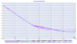
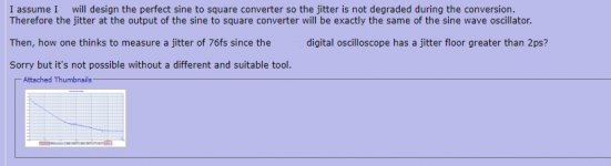
The first plot compares the phase noise of the sine wave oscillator to the square wave output from the converter.
There is no degradation in the close in phase noise, just a negligeable noise floor is added.
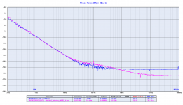
The second plot compares the phase noise of the sine wave oscillator to the square wave output from the converter/fanout buffer.
Again there is no degradation in the close in phase noise, just a little noise floor is added by the LTC6957.
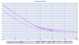
The third plot compares the phase noise of the sine wave oscillator to the BCK output from the FIFO buffer/reclocker.
The MCK was divided down by 8 so, as espected, the phase noise of the BCK is better than the one of the oscillator by several dB along all the spectrum, mostly in the close in region.
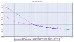
The fourth plot compares the phase noise of the sine wave oscillator to the LRCK output from the FIFO buffer.
Again, as espected, the phase noise of the LRCK is better than the one of the oscillator by several dB, mostly in the close in region. The noise floor is the same of the sine wave oscillator.
The 1/f3 noise starts below 1Hz from the carrier, where the phase noise of the LRCK is improved by 35dB, almost -130dBc at 1Hz and almost -100dBc at 0.1Hz from the carrier, that's a very good performance.
Andrea
Attachments
Instead, I'll tell you what I find infuriating about our distinguished IT with no involvement in audio whatsoever, beyond DIY. - His stubbornness to deny any commercial involvement, although everything from his messages here to his CV on LinkedIn tells a different story.
I mean there is no question of a commercial aspect to anyone despite the denial, but it is clear he means that he is not profit driven. No one can really know, but I dont think a small group buy is a very strong sign of it (the previous group buy was a once off, and they were still high performance oscillators). It is a lot different to ian or soekris.
On the other points I see your issue, in some ways I agree on his style of execution, but think that his input has been hugely valuable. While some not might not claim they or their products are the best, this image is created for them by the followers. That is the impression I get in some of Ian's threads, andrea was one of the few (maybe only one) to challenge some of the ideas. Not challenge it with 'this is snakeoil, a €50 DAC/amp will sound the same' but challenge with potential issues, suggested improvements etc. based on technical theories/concepts, sometimes measurements, not just 'this will sound worse/better'. And I understand how that could be seen as a marketing tactic... people still have to use their best judgement with any of this stuff, which you could say is still 'blind' most of the time.
And FWIW I was interested in owning a better oscillator than the standard Crysteks or NDKs before I even came across andrea's clocks.
Last edited:
Hi Andrea,
I know. You are hiding.
.....
My personal opinion? I would highly recommend people go with a similar clock and / or system from someone else that does know what they are doing. You are not really offering any design expertise or competent system design...
...
-Chris
It might be your opinion but frankly, anyone can see that the system design is of high competence; the measurements speak for themselves - if you don't get that I believe its you who need to be questioned re the technical skills... sound impact or not is an other question...
I think you have started to understand that you came in to this thread in a bit hasty manner and now you try to recover with what is a strange string of posts. I would just leave if I where you. Hat on or off. There are no extraordinary cost or level of snake oil here compared to a lot of what is going on at this forum as I see it.
//
Hi lasercut,
I have just found an answer, but it was posted a few pages before you asked your question, so I assume you have not seen it.
Not very simple to find something in such long thread.
And luckily it hasn't been flooded with 50 pages of inquisition yet.
Andrea
I have just found an answer, but it was posted a few pages before you asked your question, so I assume you have not seen it.
Not very simple to find something in such long thread.
And luckily it hasn't been flooded with 50 pages of inquisition yet.
Andrea
Attachments
- Status
- Not open for further replies.
- Home
- Source & Line
- Digital Line Level
- The Well Tempered Master Clock - Building a low phase noise/jitter crystal oscillator