Yeah, that's what I thought, the safest response to that would definitely be none.Hi lasercut,
I have just found an answer, but it was posted a few pages before you asked your question, so I assume you have not seen it.
Not very simple to find something in such long thread.
And luckily it hasn't been flooded with 50 pages of inquisition yet.
Andrea
yes, we have made several measurements of the clock signal after a simple sine to square converter (using the AC04),
You were told several times, by quite a few members, that the timepod has by design an input low pass filter.
Therefore, whatever waveform you are feeding in, you are comparing the original sine phase noise with the square wave fundamental frequency phase noise. No surprise the phase noise is quite similar (in the first two plots).
But by all means move this to the comercial sector - whatever Andrea claims...
Yes, this is what I suggested over a month ago https://www.diyaudio.com/forums/the...quality-vs-measurements-2051.html#post6677681
I know myself won't interfere with his operation there.
Guys,
I'm just not getting all the hatred here... Even if Andrea did have a commercial endeavor in the end, who cares?! He's allowed to and many designers started like this anyways (FirstOne amplifiers, Mirand products, XRK, etc...). Also, he does not owe anyone anything, he is just freely sharing with the community. No one is forced to buy (I have not bought anything) the GB products or participate. I suggest building this thread in a constructive way and not trying to bring down anything. This behavior will hopefully in return bring positive collaboration.
If you believe the claims are impossible, than know this, nothing is impossible, especially to someone who's passionate about something. This is how many ideas and discoveries were done and are still done.
Anyways, I'm not asking for any replies, just my two cents if it's worth anything...
All the best!
Do
Since the gurus here have confused ideas, the beginner tries to repeat again what was already clarified.
We have already demonstrated that the Timepod measures correctly square wave oscillators, let me recall here for the third time.
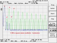
We have measured the phase noise of a 5 MHz CMOS output CTS oscillator with and without a low pass filter with 7.5 MHz corner frequency before the input of the Timepod to suppress the harmonics above its fundamental.
The first picture shows the spectrum analysis of the square wave at 5 MHz without the input filter (green curve) vs the same square wave with the filter at 7.5 MHz (blue line).
As you can see the spectrum of the signal without the low pass filter is charged with lot of harmonics, while inserting the low pass filter the harmonics practically disappear.
This means that the first 4 harmonics (10MHz, 15MHz, 20MHz and 25MHz), which have the higher energy, are not attenuated by the Timepod LPF at 27MHz.
They are captured by the ADCs exactly as are, so there is no conversion into sine wave.
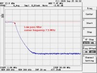
The second picture shows the AC characteristic of the filter we have used.
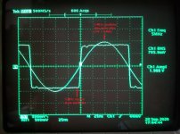
The third picture shows the oscilloscope snapshot of the waveforms.
The square wave output of the XO as is, and the sine wave obtained from the same XO filtered by a 7.5MHz low pass filter.
This means that the Timepod will measure the original XO square wave against the same square wave converted into a perfect sine wave.
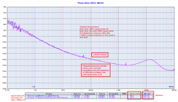
Finally the fourth picture shows phase noise and jitter comparison between the 5 MHz square wave XO with (pink line) and without (blues line) the low pass input filter.
As you see the two plots are exactly superimposed and the measured jitter is exactly the same, the harmonics of the square wave don't affect phase noise and jitter measurements in the least.
Measuring a 5 MHz square wave its harmonics fall into the passband of the input filter used in the Timepod (27MHz) but phase noise and jitter results are exactly the same, which demonstrates the reliability of the gear even with square wave clock.
I hope this helps the gurus to clarify their ideas.
I forgot: the gurus have not yet understood we are talking about PHASE noise.
We have already demonstrated that the Timepod measures correctly square wave oscillators, let me recall here for the third time.
We have measured the phase noise of a 5 MHz CMOS output CTS oscillator with and without a low pass filter with 7.5 MHz corner frequency before the input of the Timepod to suppress the harmonics above its fundamental.
The first picture shows the spectrum analysis of the square wave at 5 MHz without the input filter (green curve) vs the same square wave with the filter at 7.5 MHz (blue line).
As you can see the spectrum of the signal without the low pass filter is charged with lot of harmonics, while inserting the low pass filter the harmonics practically disappear.
This means that the first 4 harmonics (10MHz, 15MHz, 20MHz and 25MHz), which have the higher energy, are not attenuated by the Timepod LPF at 27MHz.
They are captured by the ADCs exactly as are, so there is no conversion into sine wave.
The second picture shows the AC characteristic of the filter we have used.
The third picture shows the oscilloscope snapshot of the waveforms.
The square wave output of the XO as is, and the sine wave obtained from the same XO filtered by a 7.5MHz low pass filter.
This means that the Timepod will measure the original XO square wave against the same square wave converted into a perfect sine wave.
Finally the fourth picture shows phase noise and jitter comparison between the 5 MHz square wave XO with (pink line) and without (blues line) the low pass input filter.
As you see the two plots are exactly superimposed and the measured jitter is exactly the same, the harmonics of the square wave don't affect phase noise and jitter measurements in the least.
Measuring a 5 MHz square wave its harmonics fall into the passband of the input filter used in the Timepod (27MHz) but phase noise and jitter results are exactly the same, which demonstrates the reliability of the gear even with square wave clock.
I hope this helps the gurus to clarify their ideas.
I forgot: the gurus have not yet understood we are talking about PHASE noise.
Attachments
Last edited:
Although the GB thread is already in the vendor sector, is quite curious many are asking to move this thread in the comercial sector while no one asks to move the famous FIFO buffer thread in the vendor sector.
Maybe the word "commercial" has a different meaning depending on who starts the thread.
But as I said I still don't understand what they are trying to destroy and for what reason.
Maybe the word "commercial" has a different meaning depending on who starts the thread.
But as I said I still don't understand what they are trying to destroy and for what reason.
Since the gurus here have confused ideas, the beginner tries to repeat again what was already clarified.
Exactly what I said a few posts above. Technobabble intended to impress his cheerleaders team, peppered with a personal attack.
 Thread is reopened. Please keep the discussion civil and on topic. Rules breaking posts will be removed and points awarded to their authors.
If you use the DAC in differential current mode (as intended) then it draws quite constant current from AVCC. Basically the two halves of the differential output draw complementary currents and their sum is constant (that depends on how well the two halves match, but they're on the same chip, which gives pretty good matching). If you use only one half of the differential output stage, or if you use it in voltage mode, then current is not constant, it is signal dependent, and you get extra distortion.
Do you see any way to get -30 dB/decade low-frequency noise from this?
If you have 100Hz ripple on the reference voltage then on a constant frequency test you get two spikes in the output, it looks just like jitter, but it is not. It's simply multiplication in the time domain (Vout = Vref * digital signal) corresponding to convolution of both spectra (Vref (x) digital signal).
Indeed, also known as amplitude modulation. We know from Joseph's measurements that there are -30 dB/decade noise sidebands, but not whether it is mainly phase or amplitude noise.
> Do you see any way to get -30 dB/decade low-frequency noise from this?
My low noise preamp, the one with the 20 ADA4898 op amps, had this 1 / f**3.
Scott noted that immediately. It turned out that the 100 uF foil capacitor on the
input was way to small.
It was calculated for lower -3 dB frequency. It should have been calculated for
completely shorting the bias resistor's thermal noise through the very low
impedance DUT.
This rise gives in when you get the full broadside of the 10K bias resistor
at low enough frequencies.
That required a 4700 uF wet slug tantalum for ~€110 and a lot of discipline
not to Zener the input transistors when applying a large DC input for measuring,
or shorting the input with the capacitor precharged. It also takes forever
to precharge the input RC.
BTW, with wet slug tantalums: Vishay wants about twice the money than AVX
for about the same thing. In this price league, that matters.
Gerhard
Last edited:
But by all means move this to the comercial sector - whatever Andrea claims...
//
Yes, this is what I suggested over a month ago https://www.diyaudio.com/forums/the...quality-vs-measurements-2051.html#post6677681
I know myself won't interfere with his operation there.
Is that a promise...

But seriously, this should have been done a long time ago, would've solved a lot of problems here.
The decision was made not to divulge schematics and money is being charged so seems like the appropriate thing to do.
TCD
Yes it sneaked in. I think it would be a pity if diyaudio became more of a way to introduce products for sale rather than cooperation for building things yourself. In this case there where no collaboration about a design - just promotion of products.
So moving it would be a statement.
//
So moving it would be a statement.
//
Do you see any way to get -30 dB/decade low-frequency noise from this?
No idea, depends on how the power supply reacts to the current...
Indeed, also known as amplitude modulation.
Yes.
If you see sidebands that look like jitter on both sides of a tone, repeat the test with a signal of different frequency. The amplitude of jitter sidebands is proportional to signal slew rate (ie, frequency) but the amplitude of AM sidebands due to power supply ripple does not depend on signal slew rate. So you can know if it's jitter or VREF ripple just by comparing two FFTs at different frequencies.
So moving it would be a statement.
//
True but a little late in the day. The promotional thread started a long time ago.
If you see sidebands that look like jitter on both sides of a tone, repeat the test with a signal of different frequency. The amplitude of jitter sidebands is proportional to signal slew rate (ie, frequency) but the amplitude of AM sidebands due to power supply ripple does not depend on signal slew rate. So you can know if it's jitter or VREF ripple just by comparing two FFTs at different frequencies.
Indeed, that's one reason why I started wondering if it could be the reference after seeing https://www.diyaudio.com/forums/dig...itter-crystal-oscillator-433.html#post6711314
D
Deleted member 537459
last night 2 audiophile friends listened to an Ethernet switch with Andrea's clock, compared to a switch with ocxo raltron mounted on board.
the boys didn't know anything about the test, so try blindly.
The difference is obvious. Andrea's clock has won in every respect. thanks again Andrea for the work done.
Tannoy Stirling speakers with duelund crossover
Amp accuphase a30
roon rpi4- fifopi accusilicon clock- 9038q2m dual- basesik output trasfo.
great result! next step Andrea clock for fifopi
If you see sidebands that look like jitter on both sides of a tone, repeat the test with a signal of different frequency. The amplitude of jitter sidebands is proportional to signal slew rate (ie, frequency) but the amplitude of AM sidebands due to power supply ripple does not depend on signal slew rate. So you can know if it's jitter or VREF ripple just by comparing two FFTs at different frequencies.
No. If the noise is in phase with the carrier, it's AM. If it is 90° to the carrier (quadrature)
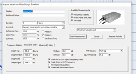
then it is phase noise. With the timepod, it's enough to click on what you want to see.
Gerhard
Attachments
Last edited:
last night 2 audiophile friends listened to an Ethernet switch with Andrea's clock, compared to a switch with ocxo raltron mounted on board.
the boys didn't know anything about the test, so try blindly.
The difference is obvious. Andrea's clock has won in every respect. thanks again Andrea for the work done.
Not only the boys knew nothing. Maybe you might consult Wikipedia to learn
how ethernet or its successors work and why the clock needs just to be good
enough that the bit error rate stays low enough to avoid retransmission.
And even then, the link is transparent with anything better than UDP protocol.
This is really offensive, like forcing a thinking being to accept that Mao, Elvis,
Santa and Mother Theresa have a great party with DT in Florida.
Gerhard
- Status
- Not open for further replies.
- Home
- Source & Line
- Digital Line Level
- The Well Tempered Master Clock - Building a low phase noise/jitter crystal oscillator