Hi Terry, I suggest you, again, to use my PS Regulator with this amp(or any other amp).
This regulator acts as a capacitance multiplier/regulator, current overload/short circuit protection and a loudspeaker DC offset protection. One PS Regulator board is enough for two TT amp channels, or it could be used two and make dual mono configuration, using one or two transformers. Probably one transformer version is cheaper and equally good and you need only one bank of big caps before the PS Regulators.
I can tell that I use TT amp together with this regulator for years now and a quiet amp became even quieter and more dynamic.
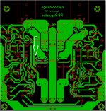
Here is the schematic, the layout and the gerbers.
BR Damir
Hi Damir,
Can you explain to me how the protection circuit works? How does it hook up to the speakers and how does it protect them?
Thanks, Terry
Hi Damir,
Can you explain to me how the protection circuit works? How does it hook up to the speakers and how does it protect them?
Thanks, Terry
Hi Terry,
Somewhere in this thread I already explained the function, but in few words it works like this.
First why this is not a regulator with fixed voltage? Instead a zener reference it uses resistor divider and capacitors only as a reference(R1, R25,R2, C1, C2 in plus side, similar in minus side). It acts as a capacitance multiplier in a way because it filters the input voltage, but follows slow input voltage change as slow change in the mains voltage or prolonged sagging under heavy load.
There three types of protection implemented:
1. Over current and short protection. Q6 is a sensing transistors reading voltage drop on R9(same in minus side) and when conducts triggers combination of Q8 and Q9(acts as SCR) and activate Q7 and shut down Q14, Q13 and output. In the same time the minus side is shutdown too via D105(the same action happens if the minus side collapses and thus close the plus side. This is actually 2. protection, always both sides are closed simultaneously.
3. Loudspeaker protection from a power amp DC offset on the output. Q11, Q12,Q101, Q102 are sensing transistors connected to the power amp output(LL, LR on the schematic). There is big RC time constant(R19, C5, R119, R105) to prevent to be triggered with music signals. Those transistors trigger the same transistors (SCR) Q8, Q9.
There is one more feature, master slave behavior as the minus side follows the plus side via P1 connected o the plus side. P1 adjust the minus side on the same plus side voltage.
BR Damir
Hi Damir,
Thanks for the explanation. How do you hook the speakers from both channels to a single protection circuit?
Hi Terry, there two inputs, LL and LR(Loudspeaker Left, Loudspeaker Right) look the schematic. I use PS regulator with three inputs for mine three channels amp.
Doh, of course.
Are you running a conventional bridge and some caps in front of this? It doesn't look like there is much of a cap to multiply.
Yes I use a bridge rectifier ad some caps http://www.diyaudio.com/forums/solid-state/182554-thermaltrak-tmc-amp-6.html#post2910364 and the photos here http://www.diyaudio.com/forums/solid-state/182554-thermaltrak-tmc-amp-7.html#post2960995
Last edited:
Hi Terry, I suggest you, again, to use my PS Regulator with this amp(or any other amp).
This regulator acts as a capacitance multiplier/regulator, current overload/short circuit protection and a loudspeaker DC offset protection. One PS Regulator board is enough for two TT amp channels, or it could be used two and make dual mono configuration, using one or two transformers. Probably one transformer version is cheaper and equally good and you need only one bank of big caps before the PS Regulators.
I can tell that I use TT amp together with this regulator for years now and a quiet amp became even quieter and more dynamic.
Here is the schematic, the layout and the gerbers.
BR Damir
In the circuit, are R26, D9 ad D10 important? If so, how critical is it that D9 be 22V?
Thanks, Terry
In the circuit, are R26, D9 ad D10 important? If so, how critical is it that D9 be 22V?
Thanks, Terry
D10 red LED indicates when the PS Regulator was switched off in case of an error triggering the protection. This schematic shows a regulator with 45 V DC input and 40 V DC output(about 5-6 V was dropped on serial transistors Q13, Q113) and D9 chose for that voltage but it's not critical, for higher voltage regulator this zener voltage should be increased accordingly. This regulator can work with higher input voltage, up to the transistors type used(BC546/556 in this case), but could be adopted for even higher voltage using higher voltage transistors.
BR Damir
I am trying to test the circuit but it is not working. It seems that D6 is reversed on your layout shown in Post 472. Can you please check that and let me know?
Thanks, Terry
D6 should be reversed, D6 and D7 are 10V zener connected back to back and if difference between + and - polarity is bigger than 10V it will trigger protection. To test the regulator first disable the protection on both polarities, by shorten R13 and R113. After that you have to adjust - polarity with P1 to be the same as + polarity (outputs of course). After that remove shorts from resistors. To test the loudspeaker protection, touch one output with one hand and with other touch in the same time one of the loudspeakers input(LL or LR). The protection should trigger and shut down the outputs. To reset the protection switch off the power and wait a bit to discharge big caps.
BR Damir
Last edited:
I'm using MJL21193/94 for the pass transistors but I have 0VBE on the MJL21194 so only about -5V output on that side. I will try shorting the protection in the morning and see it that helps find the trouble. I already spun D6 and that didn't fix it. All the transistors test right with a diode test. If I can't find the issue I will mark up a schematic and let you take a look.
Thanks, Terry
Thanks, Terry
Last edited:
I'm using MJL21193/94 for the pass transistors but I have 0VBE on the MJL21194 so only about -5V output on that side. I will try shorting the protection in the morning and see it that helps find the trouble. I already spun D6 and that didn't fix it. All the transistors test right with a diode test. If I can't find the issue I will mark up a schematic and let you take a look.
Thanks, Terry
If + and - outputs are not equal (>10 V difference) than the protection triggers and shut down both output.
BR Damir
By the way, it is good to have some loads at the outputs during testing, let say 330R 10W, or 470R 5W.
Last edited:
Hi Damir,
I tried shorting R13 and R113. I still have a issue on the - rail. I created a spice file so I would have something to compard it to but I can't get the spice file to work right. Perhaps you are someone who is better at Ltspice than I am can take a look at it and hopefully get it working so I will have a reference to help me track down what is wrong with my board.
Thanks, Terry
Attachments
Hi Damir,
I tried shorting R13 and R113. I still have a issue on the - rail. I created a spice file so I would have something to compard it to but I can't get the spice file to work right. Perhaps you are someone who is better at Ltspice than I am can take a look at it and hopefully get it working so I will have a reference to help me track down what is wrong with my board.
Thanks, Terry
Hi Terry,
I have my spice file. Just came from Classical music concert and if you put the voltage on the schematic you've got I will take a look in the morning, it's late here.
BR Damir
I'm using a variac so I just set it to 45V. That is what I put in the spice file. If you have a spice file can you just attach it and I'll use that.
Thanks, Terry
OK Terry, you don't need a variac here, no danger to burn something is not an amp. The voltages values will help. The simulation is a bit different than to simulate an amp.
Did you use a resistors to load the output. I'll be back tomorrow morning.
BR Damir
I don't have the values you listed. In the spice file I made I added 500R load resistors to the output. I get less than 2V on the outputs so something is not working.
I'll wait for spice file.
Thanks, Terry
Hi Terry,
I thought that you talked about real regulator and that you can show some voltages, but OK here are spice files: normal work, overload, and loudspeaker protection triggered.
V3 or V4 can be used to simulate an amp DC offset, used very low frequency of 0.1Hz.
BR Damir
PS. You have to click on the voltages or current to get the waveforms and values.
Attachments
Last edited:
I guess I don't know how to run this type of file because after I run it I only see 0V everywhere. I'm working on another amp right now. When I get finished with it I will measure this regulator and mark up a schematic so maybe you can help me find the issues.
Thanks, Terry
Thanks, Terry
- Status
- This old topic is closed. If you want to reopen this topic, contact a moderator using the "Report Post" button.
- Home
- Amplifiers
- Solid State
- ThermalTrak+TMC amp