Kees,
What version of Multisim do you have?
I have version 13.
regards
I zipped it from my Linux machine and apparently there is a path issue (leading slash), so I went through some convoluted extraction procedure on Windows 7 using 7zip to extract it twice. So here is a compatible Windoze zip file.The Windows' (8.1 and XP) "Compressed (zipped) Folders Extraction Wizard" says "The compressed (zipped) folder is empty". Is there something else I should be using to unzip it? 😕
Thanks Again! 🙂
Sorry about that 😀
Attachments
I've had similar problems with the Ayumi models in Micro Cap. Specifically the BM1 line: "(URAMP(V(G2,K))+1e-10)". Changing 1e-10 to 1e-03 allowed Micro Cap to converge.Has anyone been able to get the Ayumi models to work in MULTISIM? "DC sweep analysis" works great but the DC Operating point doesn't converge.😕
That didn't help - thanks for the suggestion though! 😕
I've had similar problems with the Ayumi models in Micro Cap. Specifically the BM1 line: "(URAMP(V(G2,K))+1e-10)". Changing 1e-10 to 1e-03 allowed Micro Cap to converge.
Thanks for all the models! Here’s how yours (and several others’) compare to the Philips ECC82 data sheet (http://www.drtube.com/datasheets/ecc82-philips1954.pdf). Your Mazda is almost as close as Ayumi’s. I used the 3F4 version – would you expect there to be any differences with the others? 😀
Here's a few more triode models:
Attachments
-
 Ayumi on Philips ECC82.jpg844.1 KB · Views: 460
 -
 Clay 3F4 Mazda 12AU7 on Philips ECC82.jpg786.3 KB · Views: 410
 -
 Koren Mazda 12AU7 on Philips ECC82.jpg784.7 KB · Views: 411
 -
 Clay JJ-ECC82 on Philips ECC82.jpg783.5 KB · Views: 403
 -
 Curve Capture 12AU7A GE on Philips ECC82.jpg849.8 KB · Views: 382
 -
 Koren Sylvania 12AU7 on Philips ECC82.jpg798.7 KB · Views: 178
I have not managed to find a working tube model for soviet 6P41S yet.
I have this:
.SUBCKT PENT_6P41S 1 2 3 4 ; P G K G2
+ PARAMS: CCG=3P CGP=1.4P CCP=1.9P RGI=2000
+ MU=91.184 EX=1.3719 KG1=275.0 KG2=4500.0 KP=10.65 KVB=45.0 ; Vp_MAX=420.0 Ip_M
AX=0.256 Vg_step=1.0
*--------------------------------------------------
RE1 7 0 1MEG ; DUMMY SO NODE 7 HAS 2 CONNECTIONS
E1 7 0 VALUE= ; E1 BREAKS UP LONG EQUATION FOR G1.
+{V(4,3)/KP*LOG(1+EXP((1/MU+V(2,3)/V(4,3))*KP))}
G1 1 3 VALUE={(PWR(V(7),EX)+PWRS(V(7),EX))/KG1*ATAN(V(1,3)/KVB)}
G2 4 3 VALUE={(EXP(EX*(LOG((V(4,3)/MU)+V(2,3)))))/KG2}
RCP 1 3 1G ; FOR CONVERGENCE
C1 2 3 {CCG} ; CATHODE-GRID 1
C2 1 2 {CPG1} ; GRID 1-PLATE
C3 1 3 {CCP} ; CATHODE-PLATE
R1 2 5 {RGI} ; FOR GRID CURRENT
D3 5 3 DX ; FOR GRID CURRENT
.MODEL DX D(IS=1N RS=1 CJO=10PF TT=1N)
.ENDS
But it gives an error:
Attachments
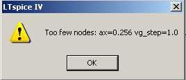
The parameters "AX=0.256 Vg_step=1.0" are on a new line, needs to be commented out as there are no corresponding 'nodes' in the subckt. Probably just a word wrap problem. 😉 Also the nodes were not in the correct order for the tetrode symbol in LTspiceI have not managed to find a working tube model for soviet 6P41S yet.
I have this:
.SUBCKT PENT_6P41S 1 2 3 4 ; P G K G2
+ PARAMS: CCG=3P CGP=1.4P CCP=1.9P RGI=2000
+ MU=91.184 EX=1.3719 KG1=275.0 KG2=4500.0 KP=10.65 KVB=45.0 ; Vp_MAX=420.0 Ip_M
AX=0.256 Vg_step=1.0
*--------------------------------------------------
But it gives an error:
Corrected below:
Code:
.SUBCKT PENT_6P41S 1 4 2 3 ; P G2 G K
+ PARAMS: CCG=3P CGP=1.4P CCP=1.9P RGI=2000
+ MU=91.184 EX=1.3719 KG1=275.0 KG2=4500.0 KP=10.65 KVB=45.0 ; Vp_MAX=420.0 Ip_M AX=0.256 Vg_step=1.0
*--------------------------------------------------
RE1 7 0 1MEG ; DUMMY SO NODE 7 HAS 2 CONNECTIONS
E1 7 0 VALUE= ; E1 BREAKS UP LONG EQUATION FOR G1.
+{V(4,3)/KP*LOG(1+EXP((1/MU+V(2,3)/V(4,3))*KP))}
G1 1 3 VALUE={(PWR(V(7),EX)+PWRS(V(7),EX))/KG1*ATAN(V(1,3)/KVB)}
G2 4 3 VALUE={(EXP(EX*(LOG((V(4,3)/MU)+V(2,3)))))/KG2}
RCP 1 3 1G ; FOR CONVERGENCE
C1 2 3 {CCG} ; CATHODE-GRID 1
C2 1 2 {CPG1} ; GRID 1-PLATE
C3 1 3 {CCP} ; CATHODE-PLATE
R1 2 5 {RGI} ; FOR GRID CURRENT
D3 5 3 DX ; FOR GRID CURRENT
.MODEL DX D(IS=1N RS=1 CJO=10PF TT=1N)
.ENDS
Last edited:


Barring syntax errors (as long as your simulator and the model you're trying to use speak the same language) there should be no difference as to what flavour of spice you use.Thanks for all the models! Here’s how yours (and several others’) compare to the Philips ECC82 data sheet (http://www.drtube.com/datasheets/ecc82-philips1954.pdf). Your Mazda is almost as close as Ayumi’s. I used the 3F4 version – would you expect there to be any differences with the others? 😀
Thanks.
I tested that and got the following errors:
Sorry that was my fault, I should have tested in LTspice before posting. 😱
The node names in the params line must match the nodes in the subckt.
Code:
.SUBCKT PENT_6P41S 1 4 2 3 ; P G2 G K
+ PARAMS: CCG=3P CGP=1.4P CCP=1.9P RGI=2000
+ MU=91.184 EX=1.3719 KG1=275.0 KG2=4500.0 KP=10.65 KVB=45.0 ; Vp_MAX=420.0 Ip_M AX=0.256 Vg_step=1.0
*--------------------------------------------------
RE1 7 0 1MEG ; DUMMY SO NODE 7 HAS 2 CONNECTIONS
E1 7 0 VALUE= ; E1 BREAKS UP LONG EQUATION FOR G1.
+{V(4,3)/KP*LOG(1+EXP((1/MU+V(2,3)/V(4,3))*KP))}
G1 1 3 VALUE={(PWR(V(7),EX)+PWRS(V(7),EX))/KG1*ATAN(V(1,3)/KVB)}
G2 4 3 VALUE={(EXP(EX*(LOG((V(4,3)/MU)+V(2,3)))))/KG2}
RCP 1 3 1G ; FOR CONVERGENCE
C1 2 3 {CCG} ; CATHODE-GRID 1
C2 1 2 {CGP} ; GRID 1-PLATE
C3 1 3 {CCP} ; CATHODE-PLATE
R1 2 5 {RGI} ; FOR GRID CURRENT
D3 5 3 DX ; FOR GRID CURRENT
.MODEL DX D(IS=1N RS=1 CJO=10PF TT=1N)
.ENDSDo you use 3F4 or 3F5?
Barring syntax errors (as long as your simulator and the model you're trying to use speak the same language) there should be no difference as to what flavour of spice you use.
Ian,
Have you compiled a personal tube library based on Curve Captor models that you would be willing to share? I design with only a handful of mainstream tubes so my personal triode library consists primarily of the 12A*7 family, the 6DJ8/6922, and the 6SN7/6CG7, all based on the Ayumi model. These have proven to be accurate enough for my purposes but I also like to have another model to run simulations against to "get a second opinion" when the results don't look quite right.
Thanks.
I mainly use this one that I found on the internet.
Cheers
Ian
Attachments
Last edited:
I mainly use this one that I found on the internet.
Cheers
Ian
Thanks, I have that library too. These models do produce results very similar to the Ayumi models and include the triodes I use most often, so I suppose I really do have what I need for the most part. I'm always looking for something better, though. 🙂
There's no preference really, I choose what will work for a specific simulator. I use mainly Micro Cap and LTspice. I have tinkered around a bit with TI's Tina.Do you use 3F4 or 3F5?
kees,
I’ve attached two Multisim circuits for doing DC Sweep analyses with cogsncogs’ models from this forum. One is his 3F4 Mazda 12AU7 (Dual Triode) Model and the other is his 6P41S (Pentode) model (I modified that one by replacing LOG with LN to keep Multisim from whining). Note that it doesn’t seem to draw any screen current though!
Depending on the version of Multisim 13 you have, you should be able to right click on the tube in the each circuit and “Save component to database” of your choosing. I’d recommend using these triode and pentode models rather than the ones in Multisim’s Master Database because Multisim’s model-symbol pin mapping is different from everyone else’s.
I’ve also attached details of the procedure that I use to generate new models. Please let me know how it works and/or what corrections it needs.😉
Jmack
I need tube models for multisim, do have someone experience to change them for multisim or now how to let them work.
thanks
kees
Attachments
kees,
I’ve attached two Multisim circuits for doing DC Sweep analyses with cogsncogs’ models from this forum. One is his 3F4 Mazda 12AU7 (Dual Triode) Model and the other is his 6P41S (Pentode) model (I modified that one by replacing LOG with LN to keep Multisim from whining). Note that it doesn’t seem to draw any screen current though!
Jmack
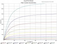
I did this really quickly, seems to be fairly close for screen current and I can't read Cyrillic very well... 😀
Code:
.SUBCKT 6P41S 1 4 2 3 ; P G2 G K
+ PARAMS: CCG=3P CGP=1.4P CCP=1.9P RGI=2000
+ MU=91.184 EX=1.3719 KG1=275.0 KG2=4500.0 KP=10.65 KVB=45.0 ; Vp_MAX=420.0 Ip_M AX=0.256 Vg_step=1.0
*--------------------------------------------------
RE1 7 0 1MEG ; DUMMY SO NODE 7 HAS 2 CONNECTIONS
E1 7 0 VALUE= ; E1 BREAKS UP LONG EQUATION FOR G1.
+{V(4,3)/KP*LN(1+EXP((1/MU+V(2,3)/V(4,3))*KP))}
G1 1 3 VALUE={(PWR(V(7),EX)+PWRS(V(7),EX))/KG1*ATAN(V(1,3)/KVB)}
*G2 4 3 VALUE={(EXP(EX*(LN((V(4,3)/MU)+V(2,3)))))/KG2}
G2 4 3 VALUE={(PWR(V(7),EX)+PWRS(V(7),EX))/KG2*(2.5708-ATAN(V(1,3)/KVB))}
RCP 1 3 1G ; FOR CONVERGENCE
C1 2 3 {CCG} ; CATHODE-GRID 1
C2 1 2 {CGP} ; GRID 1-PLATE
C3 1 3 {CCP} ; CATHODE-PLATE
R1 2 5 {RGI} ; FOR GRID CURRENT
D3 5 3 DX ; FOR GRID CURRENT
.MODEL DX D(IS=1N RS=1 CJO=10PF TT=1N)
.ENDSGot screen! 😀
I did this really quickly, seems to be fairly close for screen current and I can't read Cyrillic very well... 😀
Code:.SUBCKT 6P41S 1 4 2 3 ; P G2 G K + PARAMS: CCG=3P CGP=1.4P CCP=1.9P RGI=2000 + MU=91.184 EX=1.3719 KG1=275.0 KG2=4500.0 KP=10.65 KVB=45.0 ; Vp_MAX=420.0 Ip_M AX=0.256 Vg_step=1.0 *-------------------------------------------------- RE1 7 0 1MEG ; DUMMY SO NODE 7 HAS 2 CONNECTIONS E1 7 0 VALUE= ; E1 BREAKS UP LONG EQUATION FOR G1. +{V(4,3)/KP*LN(1+EXP((1/MU+V(2,3)/V(4,3))*KP))} G1 1 3 VALUE={(PWR(V(7),EX)+PWRS(V(7),EX))/KG1*ATAN(V(1,3)/KVB)} *G2 4 3 VALUE={(EXP(EX*(LN((V(4,3)/MU)+V(2,3)))))/KG2} G2 4 3 VALUE={(PWR(V(7),EX)+PWRS(V(7),EX))/KG2*(2.5708-ATAN(V(1,3)/KVB))} RCP 1 3 1G ; FOR CONVERGENCE C1 2 3 {CCG} ; CATHODE-GRID 1 C2 1 2 {CGP} ; GRID 1-PLATE C3 1 3 {CCP} ; CATHODE-PLATE R1 2 5 {RGI} ; FOR GRID CURRENT D3 5 3 DX ; FOR GRID CURRENT .MODEL DX D(IS=1N RS=1 CJO=10PF TT=1N) .ENDS
Attachments

- Home
- Amplifiers
- Tubes / Valves
- Vacuum Tube SPICE Models