You get asymmetric diffractionWhat happens when you have an asymmetric facets?
I doubt it is a cost cutting measure as the whole cabinet is angled and not cheap to make, probably to look different.Is it a cost cutting measure, or something else? And can it be simulated in VituixCad?
You could try to simulate a baffle with no edge radius and then another with an edge radius and a baffle just big enough for the driver as Jim did, then combine the response text files manually to the half that fits the diffraction profile.
I don't have much to add to what Fluid said. To know if it could be simulated in VituixCad we would have to compare Vcad sims to either mock-up measured data, as i did, or to BEM simulations. However, I have my doubts.Jim and others,
What happens when you have an asymmetric facets?
eg. SB Acoustics Rinjani or Ara cabinets?
Is it a cost cutting measure, or something else? And can it be simulated in VituixCad?
What's the workflow for making idealized drivers, making a diffraction model, then modeling polar response? I added two drivers to the main screen and opened the diffraction simulator, but the left side is blank and nothing happens if I try to export. Totally new to Vituicad so I could use some help.

Hi @augerproWhat's the workflow for making idealized drivers, making a diffraction model, then modeling polar response? I added two drivers to the main screen and opened the diffraction simulator, but the left side is blank and nothing happens if I try to export. Totally new to Vituicad so I could use some help.
If you haven't already seen this, here is a video which shows how to use diffraction tool.
https://www.google.com/url?sa=t&sou...xa8BegQIBBAE&usg=AOvVaw1ALokFB_Fmbg1DOZW-tptU
There are other videos also about how to use vituixcad in the above youtube channel by Kimmosto.
Regards
Vineeth
Press the new button to get a baffle, then you should see the mic and speakers as circles. It is the Sd and number of drivers in this window that matters not what you have done elsewhere. The rest should be obvious enough from the video Vineeth linked. It is the output of this window that will be used with the drivers you created elsewhere.I added two drivers to the main screen and opened the diffraction simulator, but the left side is blank and nothing happens if I try to export. Totally new to Vituicad so I could use some help.
Yeah add drivers on main window drivers tab, then highlight one, or just use the one thats already there. Then open the diffraction tool, hit new, check "feed driver" chechbox lower right coner and hit export.
tip. this will generate tons of files you might not use more than once.
I have a folder where I just export all the experiments, very rarely come back and use them again") After adjusting settings in diffraction tool just hit the export again and override the previous files or just makeup some new filename. After few tries and memorizinng few common Sd values it takes few seconds to whip up a test. Have fun!
After adjusting settings in diffraction tool just hit the export again and override the previous files or just makeup some new filename. After few tries and memorizinng few common Sd values it takes few seconds to whip up a test. Have fun!
--
Since this is your first time in Vituixcad additional tip to help finding your way through. The diffraction tool generates spinorama measurements fro you, its just a virtual spin table and its just a baffle so some effects are missing (back of the box is missing). Similar thing and data you should do for a real speaker.
What ever means you got your measurement data, did them by yourself or from diffraction tool or got them from the Internet the main window drivers are just points of origin for the measurement data. You attach a set of measurements to the driver(s), then possibly use the driver coordinate systems to orientate the set of measurements to reflect your DUT and how you took the measurements.
Now all the graphs show response on design axis and at 3meters away, or is it 2m as default, adjustable in options. Horizontal angle is adjustable top of the main window and height (vertical angle) is determined by driver y-coordinates. If you plan to listen ears at tweeter level then leave tweeter y coordinate to 0 and adjust woofers relative to that if mic was moved to drivers axis for each or left at 0 if mic wasnt moved.
The measurement data is kind of acoustic representation of your physical construct what you have measured and thats also what you are looking at in the graphs, acoustic output of your construct tuned by the filters you use.
hope it helps save some frustration!
tip. this will generate tons of files you might not use more than once.
I have a folder where I just export all the experiments, very rarely come back and use them again
After adjusting settings in diffraction tool just hit the export again and override the previous files or just makeup some new filename. After few tries and memorizinng few common Sd values it takes few seconds to whip up a test. Have fun! --
Since this is your first time in Vituixcad additional tip to help finding your way through. The diffraction tool generates spinorama measurements fro you, its just a virtual spin table and its just a baffle so some effects are missing (back of the box is missing). Similar thing and data you should do for a real speaker.
What ever means you got your measurement data, did them by yourself or from diffraction tool or got them from the Internet the main window drivers are just points of origin for the measurement data. You attach a set of measurements to the driver(s), then possibly use the driver coordinate systems to orientate the set of measurements to reflect your DUT and how you took the measurements.
Now all the graphs show response on design axis and at 3meters away, or is it 2m as default, adjustable in options. Horizontal angle is adjustable top of the main window and height (vertical angle) is determined by driver y-coordinates. If you plan to listen ears at tweeter level then leave tweeter y coordinate to 0 and adjust woofers relative to that if mic was moved to drivers axis for each or left at 0 if mic wasnt moved.
The measurement data is kind of acoustic representation of your physical construct what you have measured and thats also what you are looking at in the graphs, acoustic output of your construct tuned by the filters you use.
hope it helps save some frustration!
Last edited:
Is there any way to create an idealized driver without having to go through the whole process of entering a new driver into the database with all the TS parameters? I just want a flat frequency response and nothing else, then move on to generating the off axis responses and diffraction.
yes! thats the basic driver and situation when you dont add any actual speaker data to the diffraction tool! flat magnitude and phase from DC to infinity.
When you open up vituixcad and connect wire from source to the driver there you have it, perfect ideal pointsource without dimension. You can use this for many interesting experiments.
In diffraction tool you just give size to the ideal pointsource, make it ideal transducer, a flat disk piston or rectangle of any size, on any size baffle. Just dont load any driver data to it (in diffraction tool). Basically enter baffle dimension, driver Sd, and hit export and youve got measurements of this ideal transducer on the baffle, measured at location you put the microphone at. >If you had the "feed driver" checked you should see graphs already, in the main window.
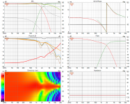
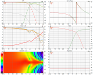
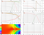
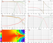
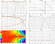
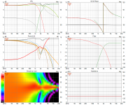
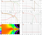
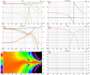
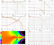
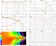
Looking for everyone's vote on which plot they prefer below. I'm specifically investigating floor and ceiling bounce, and their impact on in-room response, and DI. The models use a 6" woofer, crossed to a 4.5" midrange at 2khz. The reason for the 4.5" is that I needed something to mimic my waveguide at the crossover frequency. It rolls off fast >4khz, so just ignore that, it's not relevant to what I'm looking at anyway.
On-axis
In-room
ER Floor
ER Vertical (thick line)
ER Ceiling (thin line)
DI
On-axis
In-room
ER Floor
ER Vertical (thick line)
ER Ceiling (thin line)
DI
Attachments
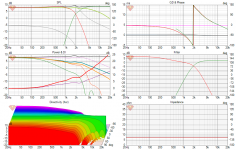
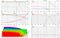
CLooking for everyone's vote on which plot they prefer below.
Brandon,
Yes VituixCAD's default is for the CTA2034A, which I feel is too generous for crossover design.
Can you make your Y axis 10dB range? If that looks too rough and ugly, 20dB?
Not 50dB, which is akin to the difference between 0.001W and 100W ie. mute to full blast. Like really?
I only care about by F3, F6, may -10dB point, not -40. And if my speaker has a 10dB peak somewhere between 20Hz to 20KHz, isn't that already bad enough? Do I really need to see more?
Last edited:
Brandon,
Can you make your Y axis 10dB range? If that looks too rough and ugly, 20dB?
Attachments

Last edited:
Why C and D?With no other information, I would go for C or D.
I would not go for A and B because of the mismatch in the DI. But E seems to have the smoothest in room response

How so?Brandon,
Yes VituixCAD's default is for the CTA2034A, which I feel is too generous for crossover design.
- Home
- Loudspeakers
- Multi-Way
- VituixCad Simulations with Ideal Drivers