Here is mabats measurements with box depth https://www.diyaudio.com/community/...-design-the-easy-way-ath4.338806/post-6972564. While there is a waveguide instead of flat disc transducer and roundovers and I don't know exactly the dimensions it looks like the deeper the box the narrower directivity is lower in frequency.
Reasoning from this, that "one doesn't want narrowing woofer response at crossover" makes the shallow box better in this regard. Deeper box seems to narrow the response lower in frequency.
Is it the diffraction hump that lessens on mabat sims? Perhaps, but it doesn't matter what it is as long as we can get the woofer and tweeter directivity match at crossover doesn't it?😀 Shallower box seems to help keep the woofer directivity wide as high in frequency as possible.
If shallow box is not possible, perhaps retrofit a pointy back, shared edge for both sides to diffract at the same time?
Hehaa, here few probes in with continuous signal. They are about the same, the triangular shows less output to side and more output to front, exact opposite as my analysis above 😀 Well, anyway, fun time experimenting 😀 Perhaps the diffraction is such a low level already on the back of the enclosure that it doesn't matter much. Seems to affect the graphs though, no idea if it is perceived by hearing system and how.
edit. added the hybrid and it has wee bit more output to side. Perhaps there is shape that helps to reduce the diffraction hump and make easier time with xo. Or just use smaller mid with smaller structure to make the diffraction hump above crossover frequency so that both woofer and tweeter are close to omni.
edit. added the hybrid and it has wee bit more output to side. Perhaps there is shape that helps to reduce the diffraction hump and make easier time with xo. Or just use smaller mid with smaller structure to make the diffraction hump above crossover frequency so that both woofer and tweeter are close to omni.
Attachments
Last edited:
Based on all the triangular and teardropish style enclosure shapes being discussed, couldn't help but share these two enclosure shapes found online. One is a diy attempt and the other is from audiosolutions vantage serries speakers.. 😀
Attachments
^And there are plenty of others. Still not sure if it is good marketing material, or for corner positioning or for real advantage over perceived sound though 🙂
Some more thoughts and investigation. Not sure if everyone knows this but since writing helps thinking I'll just write some of it here.
We often see the diffraction as ripple due to interference in some frequency response plots but not much info about the diffracted wave itself, how much it is attenuated after the corner or how loud is the "back wave". Tried to search the web but it was kind of hard to find. I've got many questions to find answers for like if the corner angle affects and what about dependency on frequency? Here is some study on edge diffraction and specifically how damping material on the edge affects Modeling Diffraction of an Edge Between Surfaces with Different Materials by Pulkki & Lokki and from the graph there it looks like attenuation of diffracted wave is frequency dependent, what a shocker 😀 Do we see this on the vituixcad sims for example? I think not, if simulated system is scaled up or down in size the amplitude of ripple stays the same. Whatta? But we see less highs on the back of cabinet than lows, does it relate or not? Its all tied together as acoustics, hard to imagine the full picture what is happening. Perhaps my tests are wrong, a strong possibility, after all this is just thought process and not exactly a scientific study.
Found another mr. Lokki paper about visualizing loudspeaker edge diffraction, and this is nice one. It was very helpful to now see how the secondary diffraction, like with back edges of a box, are very complicated as there is no point source anymore for the sound like on the baffle (considering only one transducer at a time). For secondary diffraction at the enclosure back edge the front edge (diffracted sound) works as the source for sound and it is line instead, making all kinds of paths to the side panel edges all across the surface, from any point on the baffle edge to any point on all other edges of the side.. Well, not so simple as I imagined before. Kind of a bummer, I think this is the end of trying to imagine diffraction stuff for me, for now at least 😀
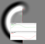
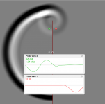
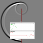
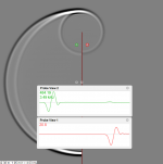
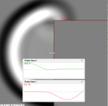
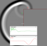
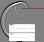
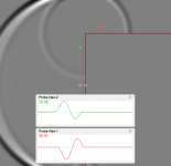
Anyway, few sims to accompany. Tried to probe attenuation of the back wave and diffracted wave with flat wall and with a corner. It looks like diffraction there is more attenuation as frequency goes up. Also it looks like the tighter the corner the more there is attenuation on the diffraction and as there is more attenuation on the diffraction (the part that goes around the corner) the more there is gain on the back wave. So much so that on a mere wall (thin box), very sharp 180 corner, the "back wave" seems to be roughly equally loud as diffracted wave (around the corner). But for typical 90 degree box corner the diffraction is louder and "back wave" less so. I've got no idea what the probe units are, but look at the ratio to see it is less with low frequency and more with high frequency. "back wave" is not seen in the green probe on these but you need to take my word on it or test yourself, it is about the same magnitude as the red probe shows with the stick experiment (180 corner) and less with the box corner experiment that is only 90 degree turn:
If there is something to learn here then perhaps it is that on a tear drop enclosure, or pointy back as I called it earlier, the sharper the corner angle on the back the more there is cancellation from the opposite side wave because "back wave" is louder for better cancellation. But, as we learned from the second paper linked above the baffle edge diffraction makes line sources as audio sources for the back edge to diffract making the waves go to multiple directions at the back and perhaps there is cancellation only in the ideal 2D plane as ripple tank but not much so in reality. For quick recap see here http://legacy.spa.aalto.fi/demos/diffr-visual/IIndorder.html a visualization how complex the secondary diffraction is, it is not just a wave going around a box like I liked to imagine until few hours a go but plane (along the side panel) going all kinds of directions 😀 Perhaps, if the box had circular symmetry hmm?
All in all, might be best to keep on looking the frequency response plots and not think too deeply on this. It is nice to have some understanding from the phenomenon so perhaps this was not time wasted. For speaker building I think the same rules of thumbs apply as earlier: if one cannot keep the structure small enough relative to wavelength, then use slants / round overs / crossovers / magic tricks in order to make smoother looking frequency response plots.
ps. diffracted sound seems to get attenuated about 20db at first tight corner / edge and less with no so tight corner. From ripple tank experiment it looks like attenuation around a corner is depending on features of the edge (angle) as well as frequency. The "back wave" seems to be the leftovers from wave that went around the corner. With sharper corner there is more attenuation around the bend and louder "back wave". This would mean easy corner has less back wave and this seems to be how round overs and slants work, less back wave. Not sure what the attenuation at secondary edge would be, perhaps another 20db or more as the sound was scattered already on the first edge. Sound around box is attenuated a lot, and smeared in time. Still, it seems to show up in frequency response plot. And still, no idea how audible any of this is. Interesting nevertheless 🙂
Some more thoughts and investigation. Not sure if everyone knows this but since writing helps thinking I'll just write some of it here.
We often see the diffraction as ripple due to interference in some frequency response plots but not much info about the diffracted wave itself, how much it is attenuated after the corner or how loud is the "back wave". Tried to search the web but it was kind of hard to find. I've got many questions to find answers for like if the corner angle affects and what about dependency on frequency? Here is some study on edge diffraction and specifically how damping material on the edge affects Modeling Diffraction of an Edge Between Surfaces with Different Materials by Pulkki & Lokki and from the graph there it looks like attenuation of diffracted wave is frequency dependent, what a shocker 😀 Do we see this on the vituixcad sims for example? I think not, if simulated system is scaled up or down in size the amplitude of ripple stays the same. Whatta? But we see less highs on the back of cabinet than lows, does it relate or not? Its all tied together as acoustics, hard to imagine the full picture what is happening. Perhaps my tests are wrong, a strong possibility, after all this is just thought process and not exactly a scientific study.
Found another mr. Lokki paper about visualizing loudspeaker edge diffraction, and this is nice one. It was very helpful to now see how the secondary diffraction, like with back edges of a box, are very complicated as there is no point source anymore for the sound like on the baffle (considering only one transducer at a time). For secondary diffraction at the enclosure back edge the front edge (diffracted sound) works as the source for sound and it is line instead, making all kinds of paths to the side panel edges all across the surface, from any point on the baffle edge to any point on all other edges of the side.. Well, not so simple as I imagined before. Kind of a bummer, I think this is the end of trying to imagine diffraction stuff for me, for now at least 😀
Anyway, few sims to accompany. Tried to probe attenuation of the back wave and diffracted wave with flat wall and with a corner. It looks like diffraction there is more attenuation as frequency goes up. Also it looks like the tighter the corner the more there is attenuation on the diffraction and as there is more attenuation on the diffraction (the part that goes around the corner) the more there is gain on the back wave. So much so that on a mere wall (thin box), very sharp 180 corner, the "back wave" seems to be roughly equally loud as diffracted wave (around the corner). But for typical 90 degree box corner the diffraction is louder and "back wave" less so. I've got no idea what the probe units are, but look at the ratio to see it is less with low frequency and more with high frequency. "back wave" is not seen in the green probe on these but you need to take my word on it or test yourself, it is about the same magnitude as the red probe shows with the stick experiment (180 corner) and less with the box corner experiment that is only 90 degree turn:


If there is something to learn here then perhaps it is that on a tear drop enclosure, or pointy back as I called it earlier, the sharper the corner angle on the back the more there is cancellation from the opposite side wave because "back wave" is louder for better cancellation. But, as we learned from the second paper linked above the baffle edge diffraction makes line sources as audio sources for the back edge to diffract making the waves go to multiple directions at the back and perhaps there is cancellation only in the ideal 2D plane as ripple tank but not much so in reality. For quick recap see here http://legacy.spa.aalto.fi/demos/diffr-visual/IIndorder.html a visualization how complex the secondary diffraction is, it is not just a wave going around a box like I liked to imagine until few hours a go but plane (along the side panel) going all kinds of directions 😀 Perhaps, if the box had circular symmetry hmm?
All in all, might be best to keep on looking the frequency response plots and not think too deeply on this. It is nice to have some understanding from the phenomenon so perhaps this was not time wasted. For speaker building I think the same rules of thumbs apply as earlier: if one cannot keep the structure small enough relative to wavelength, then use slants / round overs / crossovers / magic tricks in order to make smoother looking frequency response plots.
ps. diffracted sound seems to get attenuated about 20db at first tight corner / edge and less with no so tight corner. From ripple tank experiment it looks like attenuation around a corner is depending on features of the edge (angle) as well as frequency. The "back wave" seems to be the leftovers from wave that went around the corner. With sharper corner there is more attenuation around the bend and louder "back wave". This would mean easy corner has less back wave and this seems to be how round overs and slants work, less back wave. Not sure what the attenuation at secondary edge would be, perhaps another 20db or more as the sound was scattered already on the first edge. Sound around box is attenuated a lot, and smeared in time. Still, it seems to show up in frequency response plot. And still, no idea how audible any of this is. Interesting nevertheless 🙂
Last edited:
With your new found insights from the ripple tank simulations you may view these observation fields of different depth cabinets in a new light 🙂
https://www.diyaudio.com/community/threads/a-3-way-design-study.376620/post-6831404
Cabinets that taper to the back can indeed be beneficial
https://www.diyaudio.com/community/...ver-full-range-line-array.242171/post-6523730
Another view of a cabinet that is shorter that it is wide that can give a more cardioid like directivity over a restricted range
https://www.audiosciencereview.com/...e-platform-speaker-project.20407/post-1082442
Yeah, thanks referencing them here, need to take a new look!🙂
One more thought for the main diffraction hump, that plagues crossovers and makes system DI a hump. There really seem not to be other ways to mitigate it in a system than shift it out from crossover region either by narrowing or widening the baffle. On some of my earlier long posts I stated that "wider baffle would make woofer response narrow", which is right but not the whole truth because if the same baffle is shared with tweeter then at crossover frequency they both have same baffle related directivity don't they? Thinking about it baffle diffraction hump will be there on either the woofer or tweeter pass band or both if centered at crossover, its gonna be there because it is from the baffle and as long as sound is radiated at the baffle width wavelength to the edges to diffract a hump forms.
It still looks to me that the diffraction hump is centered at baffle width (looking at horizontal response here) at least as long as driver is center of the baffle. As I explained earlier the hump forms as half wavelength trip from transducer center to edge where "back wave" emerges with reverse polarity, which makes in phase wave towards listening spot and makes a hump, constructive interference with direct sound. But, what I didn't think earlier that if one imagines both front vertical edges of rectangular baffle (thinking horizontal response only) there is some cancellation to off-axis as well, from the same "back wave" that caused boost on-axis. Imagine both vertical edges, sound travels towards both and then the inverted "back wave" emerges form both edge traveling back to opposite direction, and the delay to sound going out from the opposite edge is of course one wavelength as the baffle width was one wavelength. This would sum up as destructive interference when observed from the side. This combination of on-axis constructive interference and off-axis destructive interference makes the response narrow at the main diffraction hump, at baffle width wavelength, and there seems to be only one way to solve it: round over, to make less "back wave", which would reduce level of the hump and increase level off-axis making wider directivity.
I think this is what kimmosto achieves with the slants / facets on small two way speaker (which I assume we are talking about): as both woofer and tweeter have shared baffle, the baffle is made as narrow as needed in order to push the diffraction hump into tweeters pass band (and out from the woofers) and then the slants are made as big as possible, since they fit beside the tweeter, to lessen the hump. Voilà, mitigated diffraction hump. If tweeter crossover is 2kHz, make the baffle 17,2cm wide and diffraction hump would be exactly at crossover, you'd want either lower crossover or narrower baffle to get the hump more into tweeters pass band. And then add slants to kill it as much as possible.
If it was 15" woofer and big waveguide system instead, you'd need to have ~40cm wide baffle to house the woofer, which would make diffraction hump around ~800Hz. Not too easy to crossover below this with 1" tweeter at least, and perhaps other directivity problems emerge (impossible to match directivities cleanly) so roundovers are mandatory for the woofer, hump needs to be dealt with on the woofer box. With passive cardioid woofer perhaps possible, use small woofer and relatively big waveguide, crossover below diffraction hump, need to investigate closer. Or just use good old big roundovers on the woofer as well.
Does this sound reasonable? Easy concept to make bumples DI: avoid main diffraction hump by reducing it with roundovers? 😀 Main baffle diffraction hump, if left into a system unattended, will show as a hump in system DI.
ps. my earlier idea that perhaps diffraction from back of the enclosure would cure the diffraction hump. This is not goonna happen because the secon order diffraction level is so low and we would have to fix both desctructive interference off-axis and constructive interference on-axis. Not gonna happen, in my imagination at least 😀
Last edited:
Ah well wrote quickly without back checking stuff. If inspecting just single ideal transducer the main diffraction hump does not create bump in DI at least with minimal baffle width, which seems to yield smoothly rising DI at least with VituixCAD diffraction tool. There is bump in on axis response and if one EQ:s on-axis flat the power response would turn out with a dip.
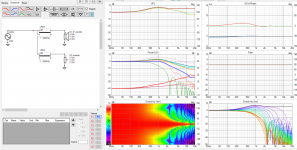
On the other hand a tweeter alone has mild DI hump around the baffle width wavelength. These are 8" and 1" ideal drivers on a 21cm wide 38cm tall baffle, no roundovers. Main diffraction hump is thus about 1.6kHz.
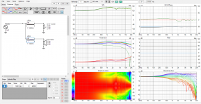
Include both drivers and crossover and things change, now there would be additional anomaly in the DI if woofer has narrower directivity than tweeter at crossover. It is just too big size difference between 8" and 1" drivers to do anything else on this than get smaller woofer or waveguide for the tweeter and try again.
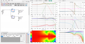
If used 5" driver instead (and smaller 13*26cm baffle) keeping the crossover the same, lot less narrowing, easier DI bump but still some. Perhaps now at limits of VituixCAD diffraction tool that cannot do partial roundovers we don't get to see what the slants would do, how much the DI hump would be reduced. Tried to emulate it with adding roundovers for the tweeter diffraction tool export but woofer response doesn't have them. Anyway, woofers response should be kept as wide as possible at crossover to reduce the hump in system DI, as much roundovers everywhere as possible 😀 and shallow cabinet would help perhaps, although not sure if it helps too much since both tweeter and woofer are on the same cabinet and the effect for both is the same, at crossover.
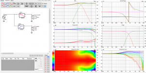
One more quickie. If chasing how to make that DI hump smaller the c-c adjustment comes in. If I raised the crossover to 2kHz to get more realistic and increase c-c distance to roughly 1.2wl then the hump is reduced some.
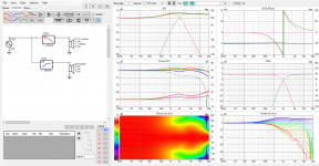
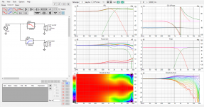
From these tests it looks like crossover would have to be a lot lower than the main diffraction hump, >2 octaves down from baffle width wavelength with the simple diffraction simulation, in order to get the narrowing completely out around crossover frequency. Not very realistic with dome tweeters at least. Fullrange driver with woofer, perhaps. Or using waveguide on the tweeter and crossing over normally.
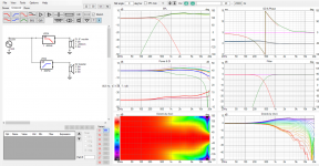
So, perhaps all these million posts arrive at simple conclusion that there is "problems" unless approaching sphere with direct radiating driver structures or using waveguides 😀 What these experiments showed it was difficult if not impossible to push the diffraction hump completely to tweeters responsibility and then kill it with roundover, within the limitations of used simulator. Some DI anomaly is expected around crossover on such speaker concept, although the DI hump was reduced some by juggling around with minimal baffle, roundovers and reducing woofer size compared to direct radiating tweeter, and finetuning c-c spacing. End of saga.

On the other hand a tweeter alone has mild DI hump around the baffle width wavelength. These are 8" and 1" ideal drivers on a 21cm wide 38cm tall baffle, no roundovers. Main diffraction hump is thus about 1.6kHz.

Include both drivers and crossover and things change, now there would be additional anomaly in the DI if woofer has narrower directivity than tweeter at crossover. It is just too big size difference between 8" and 1" drivers to do anything else on this than get smaller woofer or waveguide for the tweeter and try again.

If used 5" driver instead (and smaller 13*26cm baffle) keeping the crossover the same, lot less narrowing, easier DI bump but still some. Perhaps now at limits of VituixCAD diffraction tool that cannot do partial roundovers we don't get to see what the slants would do, how much the DI hump would be reduced. Tried to emulate it with adding roundovers for the tweeter diffraction tool export but woofer response doesn't have them. Anyway, woofers response should be kept as wide as possible at crossover to reduce the hump in system DI, as much roundovers everywhere as possible 😀 and shallow cabinet would help perhaps, although not sure if it helps too much since both tweeter and woofer are on the same cabinet and the effect for both is the same, at crossover.

One more quickie. If chasing how to make that DI hump smaller the c-c adjustment comes in. If I raised the crossover to 2kHz to get more realistic and increase c-c distance to roughly 1.2wl then the hump is reduced some.


From these tests it looks like crossover would have to be a lot lower than the main diffraction hump, >2 octaves down from baffle width wavelength with the simple diffraction simulation, in order to get the narrowing completely out around crossover frequency. Not very realistic with dome tweeters at least. Fullrange driver with woofer, perhaps. Or using waveguide on the tweeter and crossing over normally.

So, perhaps all these million posts arrive at simple conclusion that there is "problems" unless approaching sphere with direct radiating driver structures or using waveguides 😀 What these experiments showed it was difficult if not impossible to push the diffraction hump completely to tweeters responsibility and then kill it with roundover, within the limitations of used simulator. Some DI anomaly is expected around crossover on such speaker concept, although the DI hump was reduced some by juggling around with minimal baffle, roundovers and reducing woofer size compared to direct radiating tweeter, and finetuning c-c spacing. End of saga.
Last edited:
edit time over, excuse extra spam.
There might be other solutions to "problem" like this, if it is considered an issue in the first place. Perhaps use multiple reduced-diffraction structures for example, what ever that was, another study perhaps.
Hopefully @hifijim and @HeadShake link to the results they get with protypes, what their findings and thoughts are.
Roundovers do not have enough effect on the diffractive hump to make it a good approach to use a baffle the same width as the woofer the whole way unless a waveguide is used to control the pattern. Faceted baffles keep a small effective baffle size around the tweeter and is the only real way to avoid a waveguide and not have diffraction induced issues with plain tweeter.What these experiments showed it was difficult if not impossible to push the diffraction hump completely to tweeters responsibility and then kill it with roundover, within the limitations of used simulator.
Two graphs to add something to camplo's question and assumption that a wider baffle was always better and my contention that is not always the case.
A simulated SB23 driver in a 250mm wide baffle with 36mm roundovers looks quite good for the woofer, very equalizable
Make that 500mm wide and it does not so good, there is more output lower down but a peak and dip has come in, the directivity dips making the power rise so it will be impossible to juggle the on and off axis in that area.
I didn't put any real effort in to find good or bad dimensions, but it shows that wider is not automatically better, with more effort no doubt the right width of wide baffle could be found where this issue is less prominent or no existent.
Jeah, this is what I've been preaching a long time "less diffraction ripple with minimal baffle" so I very much agree 🙂
Here is when I think wider baffle ( or more like the whole enclosure ) could be justified, assuming it is part of fullrange main speaker:
So, pretty much never for me at least because big roundovers are hard to manufacture, second might be wasting good resources and third one is not practical at least for me. More studies needed to come to final conclusion so I keep right to change my mind and add to the list 😀 Perhaps big waveguide to small woofer structure (cardioidish) works fine, I have intuition for it to work but no tests yet. Might be too much waste as there is only few octaves performance below diffraction hump on cardioid / open baffle before too much bass is lost and this idea is cutting into it. With these topologies (cardioid/dipole) minimal baffle is nice because then we have most cone area for the lowest usable frequency (few octaves below main diffraction hump frequency), so most system efficiency is preserved. Imagine having 6" driver on 1 meter baffle, nice, good bass down to 4 meter wavelength but the 6" driver displacement wouldn't make too much SPL. If instead used driver with 1 meter cone without any baffle at all we would have lots of displacement at 4 meter wavelength.
Another thing, where the baffle width would not perhaps matter is if all transducers are coincident and thus have shared diffraction signature across full bandwidth, common to all transducers, for hearing system which could then perhaps ignore it all. This is just hypothesis, never searched if there is writings or studies on the idea. This might be a thing since fullrange drivers, coaxials, MEH, all kind of have it, one diffraction signature for the whole bandwidth perhaps helping it sound like one coherent sound. Even though there was lots of diffraction going on the hearing system would perhaps ignore it. Just see mark100 synergy series, it is deep into diffractoland with no roundovers but seems to have very enjoyable sound. Or fullrange lowers with all the IMD and what not, going on and uneven frequency response, but there is still something very enjoyable to it.
Here is when I think wider baffle ( or more like the whole enclosure ) could be justified, assuming it is part of fullrange main speaker:
- the widening is required to fit bigger round overs
- the driver/box is crossed over to smaller one well below diffraction.
- baffle size approaches wall size in the listening room, what ever, so that distance from driver to baffle edges is as long or longer than to room boundaries. Camplos box might fall into this category as the dimensions are about 1 meter.
So, pretty much never for me at least because big roundovers are hard to manufacture, second might be wasting good resources and third one is not practical at least for me. More studies needed to come to final conclusion so I keep right to change my mind and add to the list 😀 Perhaps big waveguide to small woofer structure (cardioidish) works fine, I have intuition for it to work but no tests yet. Might be too much waste as there is only few octaves performance below diffraction hump on cardioid / open baffle before too much bass is lost and this idea is cutting into it. With these topologies (cardioid/dipole) minimal baffle is nice because then we have most cone area for the lowest usable frequency (few octaves below main diffraction hump frequency), so most system efficiency is preserved. Imagine having 6" driver on 1 meter baffle, nice, good bass down to 4 meter wavelength but the 6" driver displacement wouldn't make too much SPL. If instead used driver with 1 meter cone without any baffle at all we would have lots of displacement at 4 meter wavelength.
Another thing, where the baffle width would not perhaps matter is if all transducers are coincident and thus have shared diffraction signature across full bandwidth, common to all transducers, for hearing system which could then perhaps ignore it all. This is just hypothesis, never searched if there is writings or studies on the idea. This might be a thing since fullrange drivers, coaxials, MEH, all kind of have it, one diffraction signature for the whole bandwidth perhaps helping it sound like one coherent sound. Even though there was lots of diffraction going on the hearing system would perhaps ignore it. Just see mark100 synergy series, it is deep into diffractoland with no roundovers but seems to have very enjoyable sound. Or fullrange lowers with all the IMD and what not, going on and uneven frequency response, but there is still something very enjoyable to it.
Last edited:
In reality that does not make the "baffle" wider but the box so the effect is more minimal.the widening is required to fit bigger round overs
^true, tried to include this info earlier on the text.
Baffle step is lowered in frequency as the box gets wider with maximally big round overs, diffraction related interference is lowered as well since round overs get equally bigger in comparison ( to the relatively flat transducer, and to wavelengths the baffle supports ), making the whole assembly approach a sphere. Playing with diffraction simulator round over radius needs to be roughly diameter of the transducer in order to get the main diffraction hump go completely away, a sphere enough.
Baffle step is lowered in frequency as the box gets wider with maximally big round overs, diffraction related interference is lowered as well since round overs get equally bigger in comparison ( to the relatively flat transducer, and to wavelengths the baffle supports ), making the whole assembly approach a sphere. Playing with diffraction simulator round over radius needs to be roughly diameter of the transducer in order to get the main diffraction hump go completely away, a sphere enough.
Last edited:
Although I have not been posting about my progress in this thread, I have been continuing to experiment with simulations.
Based on Kimmo and Fluid’s advice, I looked into making the baffle around the tweeter as small as possible. Here is an example of something that worked out pretty well. The baffle is 200 mm wide and 1000 mm tall. The edge radius/bevel is 50 mm. This means the flat portion of the baffle is just 100 mm wide, just wide enough for a typical tweeter flange.
If the tweeter were located as close to the top as possible, it would be at 900 mm (1000 mm – 50mm bevel – 50mm tweeter flange = 900 mm). However, I was able to get a little better result by moving the tweeter down a bit to 820 mm. The horizontal distance from the tweeter to the start of the bevel is 50 mm, the vertical distance from the tweeter to the start of the bevel is 130 mm. The ratio of vertical to horizontal distance is 130 / 50 = 2.6
The Sd of the hypothetical woofer is 90 cm^2, typical for a 15 cm driver. I estimate that a 20 mm radius/bevel is the largest that could be used with this driver and allow it to fit on the flat section of baffle. So in this VituixCad simulation, the tweeter has a 50 mm radius/bevel, and the midwoofer has a 20 mm radius/bevel. I am hoping that this is reasonable way to approximate slanted Avalon-style bevels.
The resulting simulated performance is quite good. The DI is +/- 1 dB from 700 Hz to 7.5 kHz. Based on the recommendation of Kimmo and Fluid, I am using a 3rd order quasi-LR filter, and using a driver spacing of 1.2 wavelength.
Now the question is whether or not this is a valid way to simulate Avalon-style bevels. I will be doing some foam-board mockups to test this, and to develop the empirical relationships to allow VituixCad to simulate this kind of cabinet baffle shape.
I have grudgingly accepted that this is true. I tried countless simulations to find a “magic combination” of baffle size/shape and crossover that would allow me to use a rectangular baffle with a 37 mm radius roundover. The best I could do was not as good as I wanted.Roundovers do not have enough effect on the diffractive hump to make it a good approach to use a baffle the same width as the woofer the whole way unless a waveguide is used to control the pattern. Faceted baffles keep a small effective baffle size around the tweeter and is the only real way to avoid a waveguide and not have diffraction induced issues with plain tweeter.
Based on Kimmo and Fluid’s advice, I looked into making the baffle around the tweeter as small as possible. Here is an example of something that worked out pretty well. The baffle is 200 mm wide and 1000 mm tall. The edge radius/bevel is 50 mm. This means the flat portion of the baffle is just 100 mm wide, just wide enough for a typical tweeter flange.
If the tweeter were located as close to the top as possible, it would be at 900 mm (1000 mm – 50mm bevel – 50mm tweeter flange = 900 mm). However, I was able to get a little better result by moving the tweeter down a bit to 820 mm. The horizontal distance from the tweeter to the start of the bevel is 50 mm, the vertical distance from the tweeter to the start of the bevel is 130 mm. The ratio of vertical to horizontal distance is 130 / 50 = 2.6
The Sd of the hypothetical woofer is 90 cm^2, typical for a 15 cm driver. I estimate that a 20 mm radius/bevel is the largest that could be used with this driver and allow it to fit on the flat section of baffle. So in this VituixCad simulation, the tweeter has a 50 mm radius/bevel, and the midwoofer has a 20 mm radius/bevel. I am hoping that this is reasonable way to approximate slanted Avalon-style bevels.
The resulting simulated performance is quite good. The DI is +/- 1 dB from 700 Hz to 7.5 kHz. Based on the recommendation of Kimmo and Fluid, I am using a 3rd order quasi-LR filter, and using a driver spacing of 1.2 wavelength.
Now the question is whether or not this is a valid way to simulate Avalon-style bevels. I will be doing some foam-board mockups to test this, and to develop the empirical relationships to allow VituixCad to simulate this kind of cabinet baffle shape.
Attachments
Sounds like progress 🙂I have grudgingly accepted that this is true.
These simulations biggest hamstring is using a flat piston to represent a dome tweeter, more corners can be added to the baffle to mimic the trapezoid shape and then a roundover. A mockup with foam sounds like a good way of seeing where the differences occur.Now the question is whether or not this is a valid way to simulate Avalon-style bevels. I will be doing some foam-board mockups to test this, and to develop the empirical relationships to allow VituixCad to simulate this kind of cabinet baffle shape.
Hifijim, nice progress!🙂 If you look at the Slide3 and 4 on your post and compare the DI graphs you'll see there is match only at about 1kHz, which would be even better crossover point in this arrangement directivity wise. You'd need smaller woofer to get the DI match higher to your crossover point, or bigger tweeter to get crossover down, basically bring the two closer in size. If you continue experimenting with simulations you could perhaps speed up the process by trying arrange as wide "flattish" DI around crossover frequency with downward slope below, for both woofer and tweeter alone, and then try to smash them together and see the complete result. However it might be either or both are impossible. Anyway, I think you'll manage so keep on doing what you already are and it is already good result, better than if you didn't focus on it at all 🙂
ps. due to 10cm flange of direct radiating tweeter you'd need about >5cm radius round over around it in order to get diffraction down just from the tweeter as you found out. Use 10cm woofer to get DI of both woofer and tweeter closer to match. This would make it 3-way system territory though as there wouldn't be much bass SPL capability on such small woofer. This is the compromise on such 2-way systems, having extended highs and lows means some compromise on mids. Pick any two from lows, highs, mids and the third has some kind of compromise requiring third way for "better performance". Third way comes with another set of compromises and you might just like the two ways better event with minor issues, they might not be that important.
Alternatively you could use waveguide to bring the tweeter size up to match bigger woofer and ability to crossover down lower, make better DI match that way. You can scale them both up in size to get more performance on bass, but after certain point you'll start losing the highs as bigger tweeter would be required to be able to slide crossover ever lower. The crossover frequency is tied to size of the two transducers basically. 1" tweeter on waveguide makes it to the upper limits of hearing and it seems one can match it to a 15" with waveguide having most extended bandwidth for a two way in that sense, and as having a waveguide the mids shouldn't bee too problematic either, use roundovers to smoothen it all up.
Last edited:
The small baffle will produce a lot of diffraction, but the location of the higher order modes affects the way they average. Your choice of simulation will show the favourable averaging.I have grudgingly accepted that this is true.
Both statements but this one mainly.The small baffle will produce a lot of diffraction, but the location of the higher order modes affects the way they average.
- Home
- Loudspeakers
- Multi-Way
- VituixCad Simulations with Ideal Drivers


