

DIY Weller WSP80 / WP80 Soldering Station
Posted 24th August 2014 at 08:58 AM by googlyone
I have been using a pretty crappy "Dick Smith" soldering iron for - well too damn long. I have always been meaning to get a decent iron. Given the fact that it worked, and I have been using it for close on 30 years (if not more) resulted in me investing my time and money in other things.
I recently bought two WSP80 Weller soldering irons off ebay at a killer price.
These ate just the "pencil" part of the soldering iron, and need the power supply / controller. Which are not cheap.
Looking on the net there are a number of schematics of various weller power supply / controllers. But various bits and pieces were not quire right for the WPS80 that I had.
As a start I am using this...
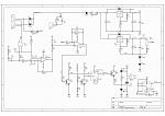
This is evidently extremely analogue. Which is quick and easy to design and build, and analogue just warms the cockles of my heart.
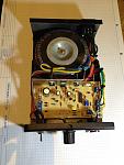
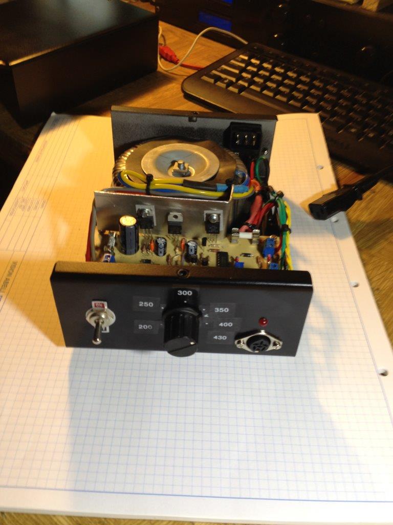
The final product is like this...

How does it work?
The iron has:
- An element
- A thermistor
The Element - pins 1 and 2 of the iron.
The plug on the Weller iron is a variant of a 6 pin DIN bayonet plug. If you get a "5 pin DIN, 240 degree" socket, then with a bit of drilling to allow the unused 6th pin to go in, you have yourself a plug.
The element is about 7 Ohms, and with 24volts RMS across it produces 80 watts of heat. The WSP80 iron is nice and small and light. The net result of this is that if you pump 80Watts into this it heats up extremely rapidly.
This thing takes about 15 seconds from cold to being at soldering temperature
The Sensor: Is connected to pins 3 and 4 of the plug.
- The room temperature resistance of this is about 22 Ohms.
- The temperature coefficient of the sensor is 0.077 ohms per degree Celsius.
So the controller needs to sense the resistance of the sensor, which will range from 22 Ohms at room temperature, up to about 53 ohms at 450 degrees Celsius.
In the circuit, a 1kilohm resistor provides a 5mA current (R5) through the sensor. This produces a voltage drop of 100 mV at room temperature up to about 250mV odd when really hot.
I will come back to this is a second...
The Power Supply - a few notes.
In the schematic there is a node "GND++" - Why? Well this circuit runs off a single rail, and most operational amplifiers are not happy with their inputs so close to the negative rail. Putting two diodes in series with the sense line does two things:
- The output voltage of the power supply is now 6.4 Volts. Which is two diode drops plus the 5V of the regulator.
- It also produces a reference voltage, which I have called GND++ at 1.4 volts above the real ground.
Back to the sensor part of the controller...
The negative pin of the amplifier (U3A pin 2) has a couple of trimpots connected to it. Why?
R13 is used to "Null" the room temperature resistance of the thermistor. Adjust it to get about the same voltage across R14 as the thermistor has.
R17 sets the gain of the sense amplifier. This needs to be adjusted such that at the maximum temperature, the output of U3A (pin 1) is about 5V, which is the maximum of the op amp.
Once the null is adjusted, this needs to be set such that at 450C the amplifier is still in the linear region (not clipping).
The Temperature set reference:
Is set by R4. The additional resistors, R28 and R11 in conjunction with the 1K pot set the range of the reference voltage for the comparator, U3B.
What do the additional resistors do? These set the upper and lower limits of temperature. It is critical that the reference temperature cannot be set too high, else the circuit will turn the heater on and leave it on. This would result in death of the iron in a very short period of time.
The 1K1 resistor sets the upper voltage such that the maximum temperature is about 450C. The lower 1K resistor sets the minimum temperature to 200C. This allows easy control of temperature using a normal potentiometer.
The Comparator:
Compares the sensed voltage via R9 to the temperature set voltage from the pot. This is output on pin 7 of U3B.
We do not want to just switch on and off the AC arbitrarily, to avoid noise we want to do this at the AC crossing point.
Zero Voltage Switching:
The circuit switches a triac on and off. To do this at zero volts, the output of the comparator is fed into the D input of a flip flop.
This flip flop is clocked using the unfiltered mains signal.
Both the D and Clock input are cleaned up and made TTL compatible using Q2 and Q3.
To increase the drive of the flip flop to allow it to drive the triac, an emitter follower is used with a 100 Ohm current limit resistor.
So there it is. Works a treat. On tests I have found that the temperature of the iron varies up and down by about +/-9C on the heat and cool cycle. Just sitting in the stand it cycles about every 20-30 seconds at a guess.
I recently bought two WSP80 Weller soldering irons off ebay at a killer price.
These ate just the "pencil" part of the soldering iron, and need the power supply / controller. Which are not cheap.
Looking on the net there are a number of schematics of various weller power supply / controllers. But various bits and pieces were not quire right for the WPS80 that I had.
As a start I am using this...

This is evidently extremely analogue. Which is quick and easy to design and build, and analogue just warms the cockles of my heart.
The final product is like this...

How does it work?
The iron has:
- An element
- A thermistor
The Element - pins 1 and 2 of the iron.
The plug on the Weller iron is a variant of a 6 pin DIN bayonet plug. If you get a "5 pin DIN, 240 degree" socket, then with a bit of drilling to allow the unused 6th pin to go in, you have yourself a plug.
The element is about 7 Ohms, and with 24volts RMS across it produces 80 watts of heat. The WSP80 iron is nice and small and light. The net result of this is that if you pump 80Watts into this it heats up extremely rapidly.
This thing takes about 15 seconds from cold to being at soldering temperature
The Sensor: Is connected to pins 3 and 4 of the plug.
- The room temperature resistance of this is about 22 Ohms.
- The temperature coefficient of the sensor is 0.077 ohms per degree Celsius.
So the controller needs to sense the resistance of the sensor, which will range from 22 Ohms at room temperature, up to about 53 ohms at 450 degrees Celsius.
In the circuit, a 1kilohm resistor provides a 5mA current (R5) through the sensor. This produces a voltage drop of 100 mV at room temperature up to about 250mV odd when really hot.
I will come back to this is a second...
The Power Supply - a few notes.
In the schematic there is a node "GND++" - Why? Well this circuit runs off a single rail, and most operational amplifiers are not happy with their inputs so close to the negative rail. Putting two diodes in series with the sense line does two things:
- The output voltage of the power supply is now 6.4 Volts. Which is two diode drops plus the 5V of the regulator.
- It also produces a reference voltage, which I have called GND++ at 1.4 volts above the real ground.
Back to the sensor part of the controller...
The negative pin of the amplifier (U3A pin 2) has a couple of trimpots connected to it. Why?
R13 is used to "Null" the room temperature resistance of the thermistor. Adjust it to get about the same voltage across R14 as the thermistor has.
R17 sets the gain of the sense amplifier. This needs to be adjusted such that at the maximum temperature, the output of U3A (pin 1) is about 5V, which is the maximum of the op amp.
Once the null is adjusted, this needs to be set such that at 450C the amplifier is still in the linear region (not clipping).
The Temperature set reference:
Is set by R4. The additional resistors, R28 and R11 in conjunction with the 1K pot set the range of the reference voltage for the comparator, U3B.
What do the additional resistors do? These set the upper and lower limits of temperature. It is critical that the reference temperature cannot be set too high, else the circuit will turn the heater on and leave it on. This would result in death of the iron in a very short period of time.
The 1K1 resistor sets the upper voltage such that the maximum temperature is about 450C. The lower 1K resistor sets the minimum temperature to 200C. This allows easy control of temperature using a normal potentiometer.
The Comparator:
Compares the sensed voltage via R9 to the temperature set voltage from the pot. This is output on pin 7 of U3B.
We do not want to just switch on and off the AC arbitrarily, to avoid noise we want to do this at the AC crossing point.
Zero Voltage Switching:
The circuit switches a triac on and off. To do this at zero volts, the output of the comparator is fed into the D input of a flip flop.
This flip flop is clocked using the unfiltered mains signal.
Both the D and Clock input are cleaned up and made TTL compatible using Q2 and Q3.
To increase the drive of the flip flop to allow it to drive the triac, an emitter follower is used with a 100 Ohm current limit resistor.
So there it is. Works a treat. On tests I have found that the temperature of the iron varies up and down by about +/-9C on the heat and cool cycle. Just sitting in the stand it cycles about every 20-30 seconds at a guess.
Total Comments 2
Comments
-
 Good work! Simple and reliable! Can you see the file of the PCB of the soldering station?
Thank you!Posted 24th September 2015 at 03:13 AM by braslet

-
Good work! Simple and reliable! Can you see the file of the PCB of the soldering station?
Thank you!Posted 9th October 2015 at 03:12 AM by braslet

