

DIY Audio Analyser using CS4398 / CS5381 - The Limits of These IC's
Posted 6th September 2015 at 11:47 AM by googlyone
Updated 6th September 2015 at 11:56 AM by googlyone
Updated 6th September 2015 at 11:56 AM by googlyone
I have had the time to play with the MiniDSP Streamer and my ADC and DACs now.
Initial results were disappointing - and led to me looking very closely at the ADC drive, and particularly the single ended to differential part of the circuit.
Given I pinched this circuit from an application note (and embarrassingly did not question it adequately) gives me little solace that I built, and used this!
Interestingly, Creative Labs did exactly the same thing on the sound blaster that I had so much trouble improving - the single ended conversion is just wrong. This solves the "Puzzle" that I noted in a blog a few months ago - now I know why I just couldn't get better performance out of that CS5381 drop in to the Sound blaster box.
In the process of improving the ADC drive, and to allow experimentation with the input op amps, I built two versions of the ADC drive, one using non inverting buffers and a second that uses inverting buffers - much as AKM recommend for the AK5394/7.
- This allowed me to try a range of op amps, but I have focussed on LM4562 and NE5532
- The inverting version keeps the drive op amps with very little common mode input voltage.
- Both versions deliver a low impedance drive to the ADC.
The reason I did both was that I found a LOT of sensitivity to this drive. It is apparent that the input to the CS5381 is a very, very hard load to drive. I would suggest from what I have seen that this is a significant difference between this IC and the CS5361.
Given I was pretty sure I would be mucking around with the design, I did these PCB's in the shed. Two reasons:
- It is FAST, I can fabricate an unladed double sided board in a morning (given have the PCB designed)
- It is cheap -- MOQ=1! I usually make two or four, as the delta in effort is about half an hour.
If I settle on a design I will likely get a small batch made up in a factory. Mainly because it looks pretty, but I can also use more than double sided.
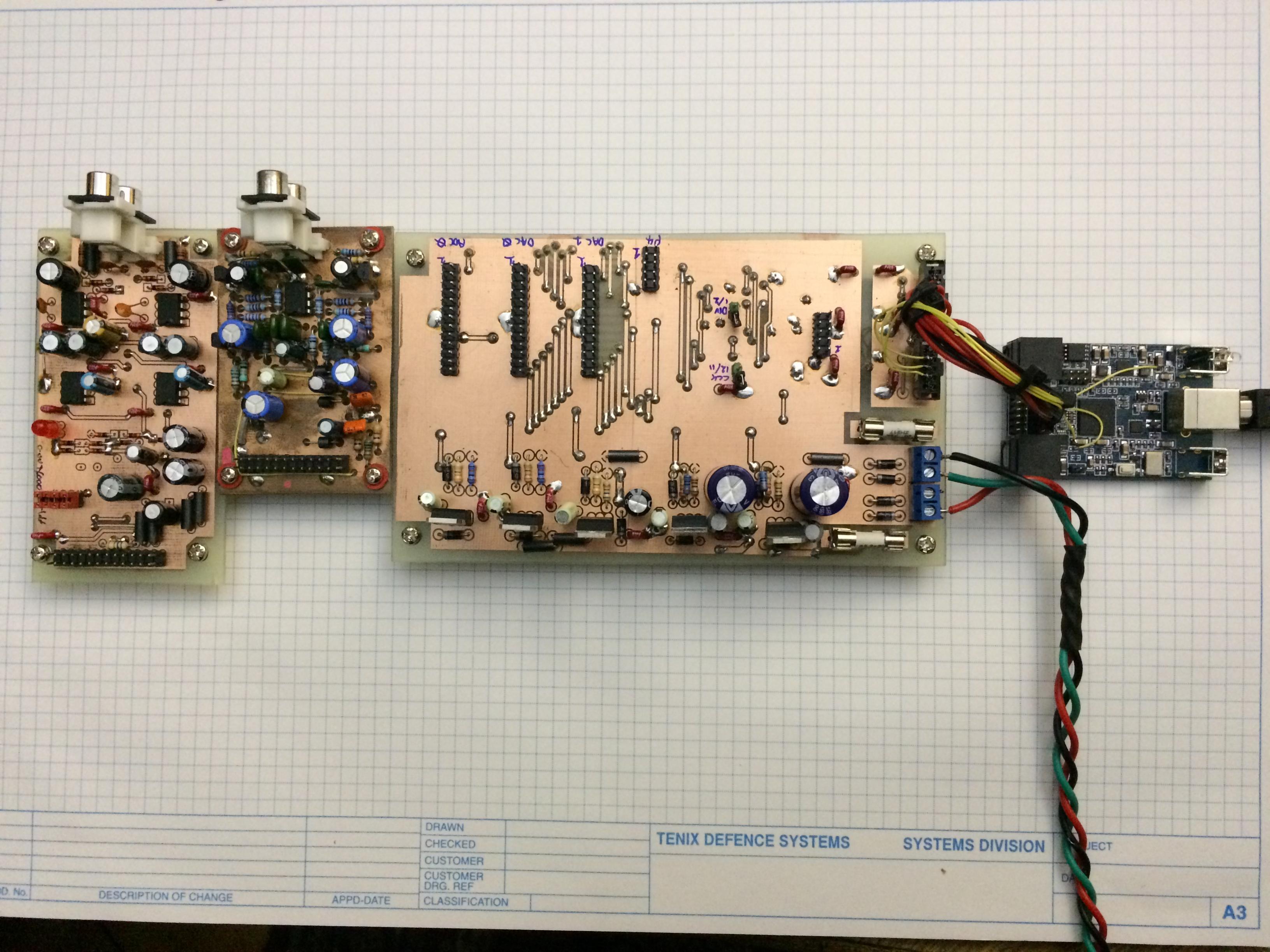
What did I end up with as the ADC?
This:
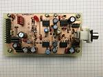
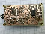
Ok, it is not an awful lot to look at. Most of it is surface mount on the back...
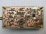
Which is only mildly more exciting.
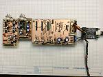
The thing is not a massive beauty, but it works. As do the other seven boards - seems I got out of control Four of each as noted above have inverting and non inverting ADC drivers.
The line-up is:
PC --> MiniDSP Streamer --> Interface / PSU board --> ADC and DAC
The ADC is CS5381 (and a CS5361 on a couple of biards). The DAC is CS5398.
How did it go?
Well, I am pretty sure I have run the CS parts down to their limits now.
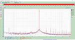
And the noise floor (one channel shorted on the ADC) is reasonable:
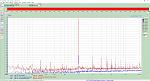
Those with a keen eye will note that the noise floor around the first distortion plot above is different to the second.
This is a result of the fact this plot is generated with a Q=5 bandpass filter inserted between the DAC and ADC. I was trying to get the distortion lower than the CS5398.
A few observations:
- From chip to chip there seems to be variation in the "sweet spot" for the CS5381. This tends to be between -5 and -10dBc or so.
- Pretty well all the devices on loopback are able to measure better than -100dBc, with pretty well all exhibiting -104dBc at some region of I/O level.
- There is an interesting dependency on driving one or both channels of the ADC. There is a definite benefit in driving both channels from exactly the same input signal. It is not clear to me if this is a crosstalk effect, or some other form of interaction. It is a LONG way down, and I wonder if the designers of the IC decided to just live with this.
- The absence of a screened box is quite apparent - you can see that I live in Australia and we have 50Hz mains electricity!
- For one board I did not have the 2n7 capacitor across the ADC input - without this there is MASSES of noise and the distortion spurs come up to about -70dBc. This part of the circuit is clearly super important!
I have been playing with different capacitors in the buffers and across the ADC differential inputs. There are measurable differences - but it is probably going to be a long and tedious process to work out what is "best".
So the measured loopback response is essentially -104dBc, or about 0.0006% give or take. And depending on where the other ADC channel is driven from, and the level...
So where next. Unless someone is going to throw some more light on these devices, I suspect that this is about as good as it gets with them.
As an illustration of the mucking around I have gone through - here is a photo of a "non inverting buffered" version of the same board:
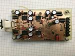
The only real differences are:
- CS5381 in a more sensible package for hand soldering
- Different arrangement of the buffers.
- The %$#@ up on the location of the 100k resistor on the input buffer fixed.
Amongst all these boards I have tried NE5532 and LM4562 op amps. To be honest, in this circuit there is not an immediately apparent difference. Though I suspect I will live to regret those words...
Once I have recovered from the effort of running around making all these boards, I will look at the AKM ADC and DACs. I am just a it fearful that there will be the same level of contortionism to get really low levels of distortion from these just as I have seen with the CS parts.
Perhaps just for now I should package this up into a distortion analyser, and learn to live with this as the limit of performance of the system.
Initial results were disappointing - and led to me looking very closely at the ADC drive, and particularly the single ended to differential part of the circuit.
Given I pinched this circuit from an application note (and embarrassingly did not question it adequately) gives me little solace that I built, and used this!
Interestingly, Creative Labs did exactly the same thing on the sound blaster that I had so much trouble improving - the single ended conversion is just wrong. This solves the "Puzzle" that I noted in a blog a few months ago - now I know why I just couldn't get better performance out of that CS5381 drop in to the Sound blaster box.
In the process of improving the ADC drive, and to allow experimentation with the input op amps, I built two versions of the ADC drive, one using non inverting buffers and a second that uses inverting buffers - much as AKM recommend for the AK5394/7.
- This allowed me to try a range of op amps, but I have focussed on LM4562 and NE5532
- The inverting version keeps the drive op amps with very little common mode input voltage.
- Both versions deliver a low impedance drive to the ADC.
The reason I did both was that I found a LOT of sensitivity to this drive. It is apparent that the input to the CS5381 is a very, very hard load to drive. I would suggest from what I have seen that this is a significant difference between this IC and the CS5361.
Given I was pretty sure I would be mucking around with the design, I did these PCB's in the shed. Two reasons:
- It is FAST, I can fabricate an unladed double sided board in a morning (given have the PCB designed)
- It is cheap -- MOQ=1! I usually make two or four, as the delta in effort is about half an hour.
If I settle on a design I will likely get a small batch made up in a factory. Mainly because it looks pretty, but I can also use more than double sided.
What did I end up with as the ADC?
This:

Ok, it is not an awful lot to look at. Most of it is surface mount on the back...
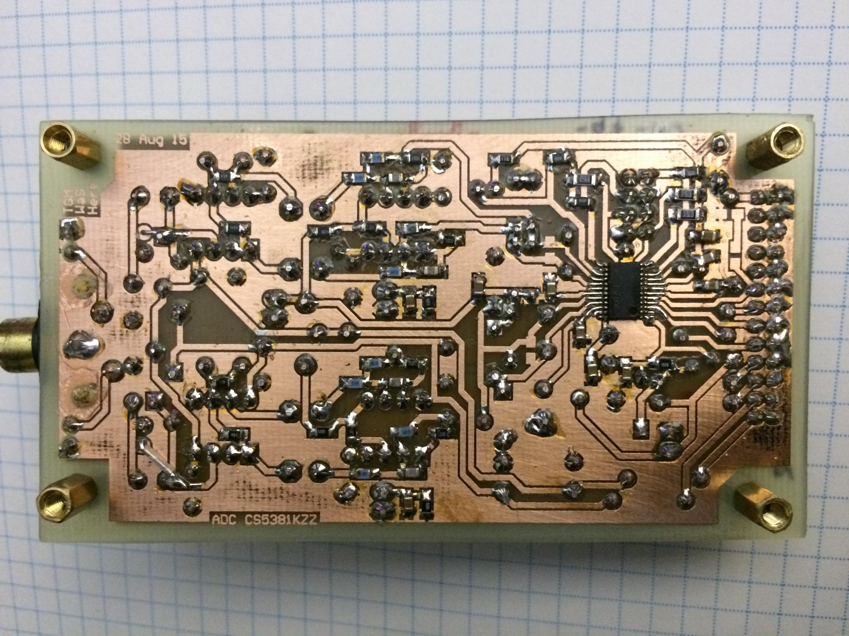
Which is only mildly more exciting.
The thing is not a massive beauty, but it works. As do the other seven boards - seems I got out of control
Four of each as noted above have inverting and non inverting ADC drivers.The line-up is:
PC --> MiniDSP Streamer --> Interface / PSU board --> ADC and DAC
The ADC is CS5381 (and a CS5361 on a couple of biards). The DAC is CS5398.
How did it go?
Well, I am pretty sure I have run the CS parts down to their limits now.
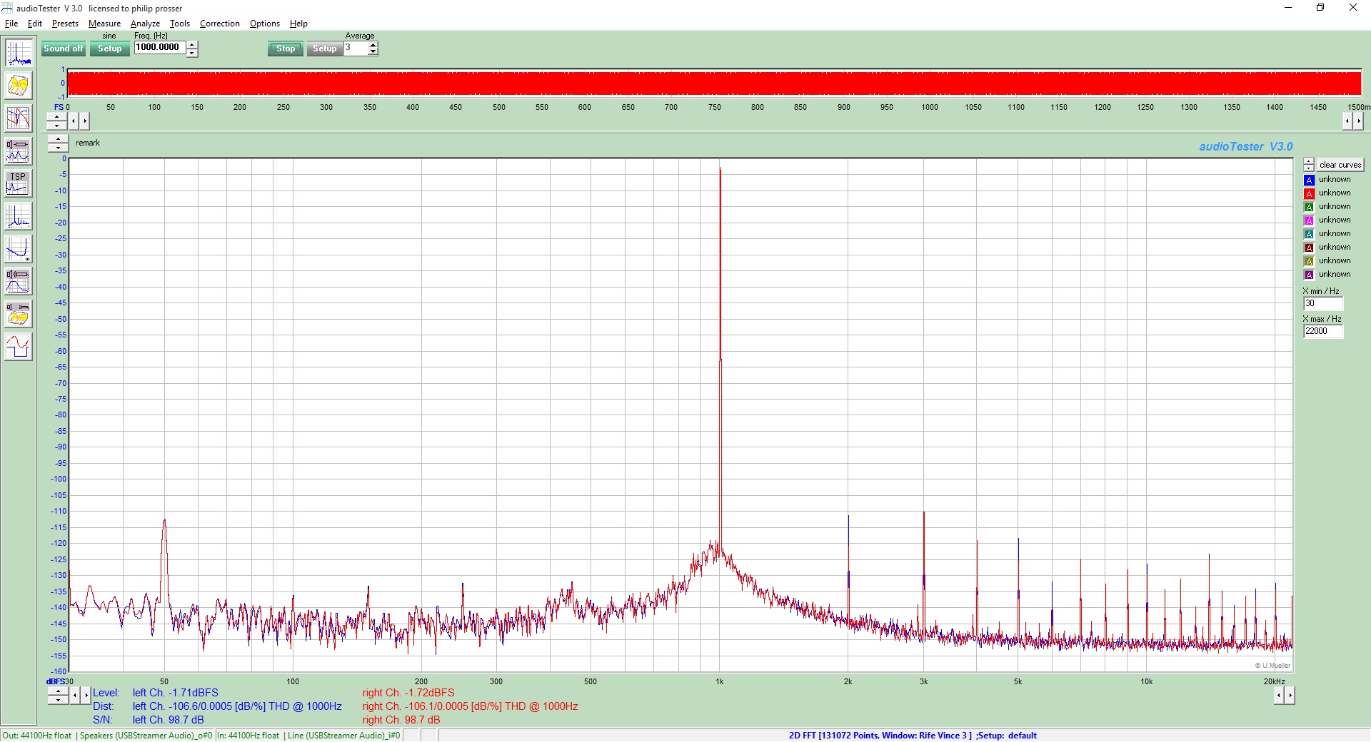
And the noise floor (one channel shorted on the ADC) is reasonable:
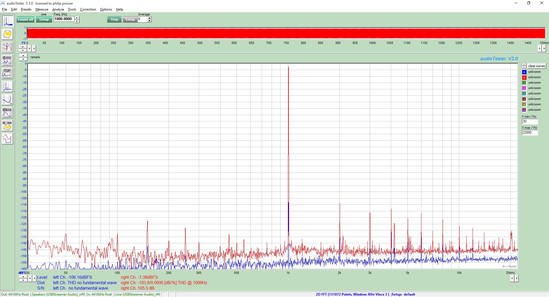
Those with a keen eye will note that the noise floor around the first distortion plot above is different to the second.
This is a result of the fact this plot is generated with a Q=5 bandpass filter inserted between the DAC and ADC. I was trying to get the distortion lower than the CS5398.
A few observations:
- From chip to chip there seems to be variation in the "sweet spot" for the CS5381. This tends to be between -5 and -10dBc or so.
- Pretty well all the devices on loopback are able to measure better than -100dBc, with pretty well all exhibiting -104dBc at some region of I/O level.
- There is an interesting dependency on driving one or both channels of the ADC. There is a definite benefit in driving both channels from exactly the same input signal. It is not clear to me if this is a crosstalk effect, or some other form of interaction. It is a LONG way down, and I wonder if the designers of the IC decided to just live with this.
- The absence of a screened box is quite apparent - you can see that I live in Australia and we have 50Hz mains electricity!
- For one board I did not have the 2n7 capacitor across the ADC input - without this there is MASSES of noise and the distortion spurs come up to about -70dBc. This part of the circuit is clearly super important!
I have been playing with different capacitors in the buffers and across the ADC differential inputs. There are measurable differences - but it is probably going to be a long and tedious process to work out what is "best".
So the measured loopback response is essentially -104dBc, or about 0.0006% give or take. And depending on where the other ADC channel is driven from, and the level...
So where next. Unless someone is going to throw some more light on these devices, I suspect that this is about as good as it gets with them.
As an illustration of the mucking around I have gone through - here is a photo of a "non inverting buffered" version of the same board:
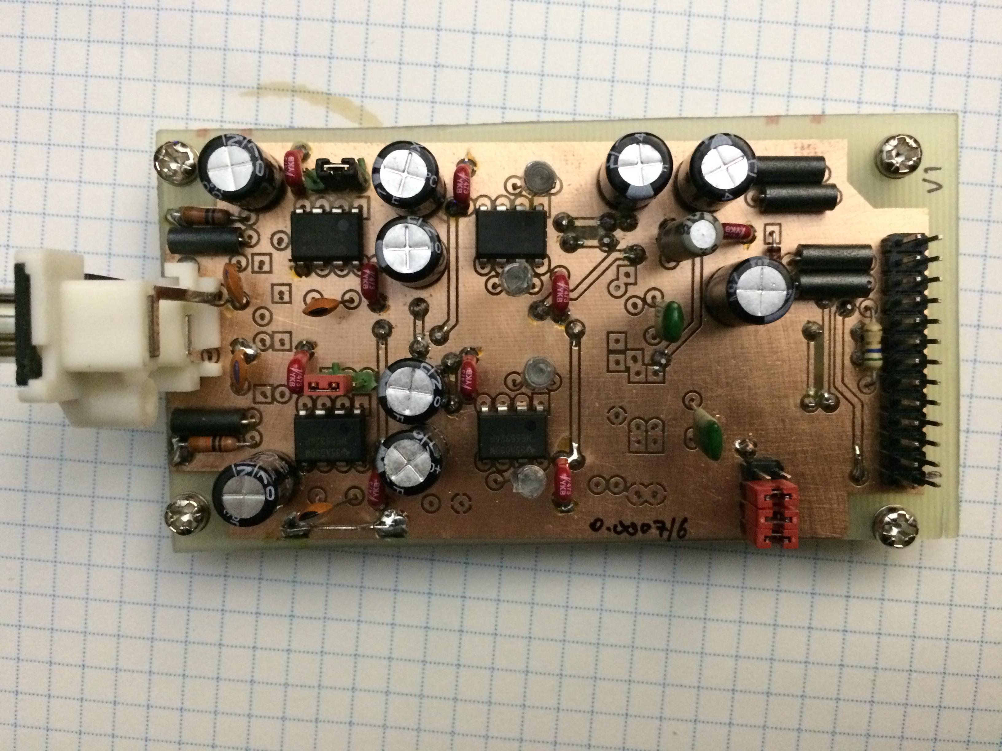

The only real differences are:
- CS5381 in a more sensible package for hand soldering
- Different arrangement of the buffers.
- The %$#@ up on the location of the 100k resistor on the input buffer fixed.
Amongst all these boards I have tried NE5532 and LM4562 op amps. To be honest, in this circuit there is not an immediately apparent difference. Though I suspect I will live to regret those words...
Once I have recovered from the effort of running around making all these boards, I will look at the AKM ADC and DACs. I am just a it fearful that there will be the same level of contortionism to get really low levels of distortion from these just as I have seen with the CS parts.
Perhaps just for now I should package this up into a distortion analyser, and learn to live with this as the limit of performance of the system.
Total Comments 0


