Go Back   Home > Forums > Blogs

Old

The B1 active XO's

Posted 23rd November 2009 at 07:26 PM by relder (Rob's active 3way with transconductance chipamps build blog)

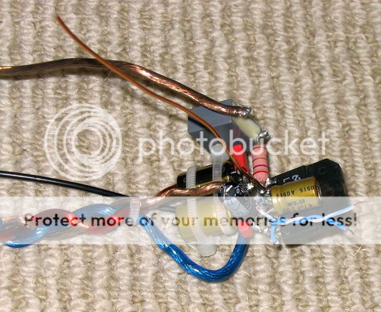
Tony asked about the B1 active XO's. There's really not much to say. Any active filter that uses an opamp as a buffer (I.e. where output is directly tied to the '-' input) AND a cap blocks DC from the output to the feedback loop should be able to use a B1 like buffer. The circuits in sections 1, 2, 3 and 7 of SL's filter page all qualify, but the rest may be sketchy in my mind since the B1 can have some DC offset.

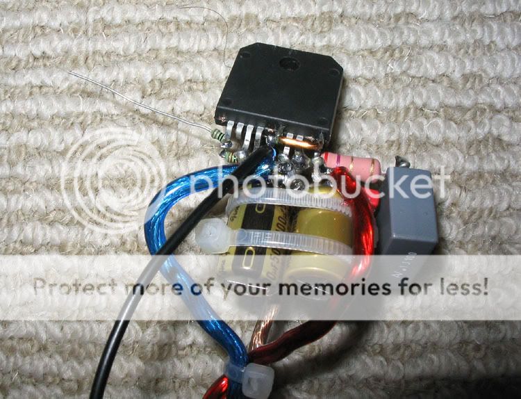
Attached is a rough drawing I scribbled last night for my own benefit, so it ain't pretty. An input buffer is something I'm still debating needing or not, but I'm leaving some room for it.

I'm going to let Soundeasy help me define the values, but the drivers are pretty well behaved in their desired bandwidth such that nearly textbook filters can be used.

I don't have enough JFETs of any one type for everything, so I'm going to have to mix types, probably LSK170s for the woofer and Toshi 2SK170s for the mid/tweet.

...
Attached Thumbnails
Click image for larger version

Name:	XOdrawing.gif
Views:	787
Size:	40.9 KB
ID:	53  
relder's Avatar
diyAudio Member
Posted in 3 Way
Views 1563 Comments 2 relder is offline
Old

my projects:

Posted 22nd November 2009 at 03:20 AM by Bigun

Head Amp: https://www.diyaudio.com/forums/aksa/...phone-amp.html
Speaker: https://www.diyaudio.com/forums/showt...ght=Moon+onken
Sub: https://www.diyaudio.com/forums/showt...hreadid=140069
TGM Amp: https://www.diyaudio.com/forums/showt...ight=amplifier
Harry77 Amp:https://www.diyaudio.com/forums/solid...arry-77-a.html
Bigun's Avatar
diyAudio Member
Posted in Uncategorized
Views 14323 Comments 10 Bigun is offline
Old

pictures

Posted 21st November 2009 at 09:14 PM by tomtt
Updated 5th February 2011 at 09:41 PM by tomtt

Click the image to open in full size.

Click the image to open in full size.

Click the image to open in full size.

Click the image to open in full size.

Click the image to open in full size.

Click the image to open in full size.

Click the image to open in full size.

Click the image to open in full size.


From Here -

Ace High Dishes | Abandoned Britain - Photographing Ruins


https://missanielablog.com/shooting-visions-of-trees


Abandoned Britain - Photographing Ruins


https://translate.googleusercontent.c...1TBHDJQSOg_AKA...
tomtt's Avatar
diyAudio Member
Posted in Uncategorized
Views 854 Comments 0 tomtt is offline
Old

Build your own case

Posted 20th November 2009 at 09:52 PM by DougL

https://www.diyaudio.com/forums/const...ml#post1987690

These are answers I need.

Thanks.
diyAudio Member
Views 732 Comments 0 DougL is offline
Old

Delivery

Posted 20th November 2009 at 07:48 PM by Bas Horneman (Bas Horneman's diyAudio.com blog)

Look what the mailman/woman dropped at my casa.

A matched quartet of GM70's (Almost ashamed at how little I paid for them) GM70's are for a SE GM70 amp with MQ parafeed iron.

And the 500R trimpots and 0,22uF caps for the Baby Huey.

Click the image to open in full size.
Attached Thumbnails
Click image for larger version

Name:	delivered.jpg
Views:	8252
Size:	94.8 KB
ID:	52  
Bas Horneman's Avatar
diyAudio Moderator Emeritus
Posted in Buying
Views 788 Comments 0 Bas Horneman is offline
Old

To do

Posted 20th November 2009 at 03:53 PM by relder (Rob's active 3way with transconductance chipamps build blog)

A main reason I'm active on this project is the event coming up on the 5th. For me there's nothing like a deadline to get me out in the garage.

A lot left to do:
  • MLS measurements - on/off axis at varying output impedances for 3 drivers will make for quite a few measurements
  • Figure out how to enclose the mid - I'm thinking open back at the moment
  • Design the active crossovers in Soundeasy
  • Build the active XOs - point to point likely using FirstWatt B1 type buffers (two JFETs isn't much more work than an opamp)
  • Paint

Two weeks left!
relder's Avatar
diyAudio Member
Posted in 3 Way
Views 1090 Comments 1 relder is offline
Old

Construction of a P2P LM3886 gainclone part 2.

Posted 20th November 2009 at 03:44 AM by wintermute (Wintermutes Rantings)
Updated 25th November 2009 at 12:18 PM by wintermute (Added to category amplifiers)

edit: applogies to anyone viewing this at less than 1280 screen width... It formats properly with that (two images side by side) but I'm not going to go and redo all the images now!!! I already did twice....

OK Continuing on where Part 1 left off. The next step was to attach the Power Supply wiring. I will continue the numbering from the first blog entry for consistency.

18. Click the image to open in full size. 19. Click the image to open in full size.

images 18 and 19 show the completed amplifier with +ve -ve and zero volts wires connected. Note also that there is a separate zero volts return from the zobel capacitor to the star ground on the PS board. The red wire is the +ve the blue wire the -ve and the green wire is the zero volts. The return for the speakers is direct from the speaker output jack to the star point on the PS board. So in all there...
wintermute's Avatar
diyAudio Moderator
Posted in amplifiers
Views 10288 Comments 6 wintermute is offline
Old

Construction of a P2P LM3886 gainclone part 1.

Posted 19th November 2009 at 09:18 AM by wintermute (Wintermutes Rantings)
Updated 17th April 2011 at 01:19 PM by wintermute (Added to category amplifiers)

edit: 17th April 2011. Just to set the record straight, although I refer to this chipamp as a "gainclone" strictly speaking it is not. A gainclone is I believe actually a clone of the 47 labs gaincard, however many people refer to chipamps as gainclones incorrectly (myself included).

edit: apologies to anyone viewing this at less than 1280 screen width... It formats properly with that (two images side by side) but I'm not going to go and redo all the images now!!! I already did twice....

Well I said about 4 years ago that I would do a build writeup for my P2P gainclone. I took all of the pictures but never got around to it. I'm off sick and lacking energy so decided it was as good a time as any to have a crack at it

I started out with the BrianGT schematic. I wanted to build something that people were using and was likely to just work. Here is a copy of the schematic
Click the image to open in full size....
wintermute's Avatar
diyAudio Moderator
Posted in amplifiers
Views 16077 Comments 6 wintermute is offline
Old

Ordered 500R pots for the driver stage.

Posted 18th November 2009 at 09:27 AM by Bas Horneman (Bas Horneman's diyAudio.com blog)

And while I was at it I saw some 0,22uF Epcos MKV from the same seller. The Epcos will do duty as coupling cap, as I've seen good reports (anecdotal) on them.

I asked Ian (gingertube) what the 470R resistors were for. Because I figured the CCS would take care of everything of the balance.

Here was his answer:
Quote:
The 1K pot is to set balance in the diff amp. The resistance in the triode cathode degenerates the tube gm (Ia/Vgk). Sweeping the pot wiper from side to side varies the amount of degeneration on each of the 2 triodes until they match. This is the minimum distortion condition for the diff amp. As we don't want to throw away gm un-necessarily we don't want those resistance values too high - just high enough to be able to adjust for matching behavior.
For a random sampling of 12AX7 and ECC803S that I had, 1K was too much, 100R was'nt quite enough so I dropped the 470R on each side of the 1K pot which effectively makes that pot about
...
Attached Thumbnails
Click image for larger version

Name:	500r.jpg
Views:	516
Size:	17.0 KB
ID:	49   Click image for larger version

Name:	epcos.jpg
Views:	521
Size:	12.0 KB
ID:	50   Click image for larger version

Name:	cepcos.jpg
Views:	351
Size:	11.3 KB
ID:	51  
Bas Horneman's Avatar
diyAudio Moderator Emeritus
Posted in Buying
Views 738 Comments 0 Bas Horneman is offline
Old

Slowly but surely making progress

Posted 16th November 2009 at 10:36 PM by Bas Horneman (Bas Horneman's diyAudio.com blog)

I have used a diy fluid for drilling for the first time. Used bicycle chain oil...water and detergent. Quite happy with it. Drilled the largest hole yet. And it looked almost professional.

Also a photo of the oak enclosure after it was treated with boiled linseed oil. The oil makes the oak enclosure look a lot better, it really brings out the grain. As usual I don't have "before" pictures to show the difference. (the pictures below had a partial coat already)

I'm not sure what to seal the wood with. Suggestions are welcome. Right now I'm thinking about shellac.
Attached Thumbnails
Click image for larger version

Name:	moreholes.jpg
Views:	414
Size:	68.3 KB
ID:	47   Click image for larger version

Name:	grain.jpg
Views:	391
Size:	35.7 KB
ID:	48  
Bas Horneman's Avatar
diyAudio Moderator Emeritus
Posted in Building
Views 647 Comments 0 Bas Horneman is offline

New To Site? Need Help?
Copyright ©1999-2017 diyAudio