hello sit that is actually a change I did to the file myself from mister Willy I do have the files gerbers and Sprint file if want too I'll attached them here")
Is the pcb tested to work ?
the parts are changed, not able to follow the layout vs the AX11 schematic listed in the apex directory thread.
do you have updated schematic ?
thanks.
bias
Can you say how to set up the bias and other important things, thanks and regards.
Anoop
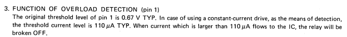
Hi APEX,Ultimate Fidelity with MOSFETs
Can you say how to set up the bias and other important things, thanks and regards.
Anoop
With overcurrent cut-out protect, and power increase up to 100W/8R...
Mr. Miles,
can this over current protection be used with UPC1237 , if not what changes can be made? here is pic of datasheet. and link http://www.tecnotre.it/audio/tecnica/upc1237.pdf
reg
Prasi
Attachments
Last edited:
upc1237 does not have built-in OCP, as they say, due to patent reasons, you have to add external ckts to sense the V across the emitter R or other means to determine a OC condition and then drive pin 1, past 0.67V to de-energize the relay.
For an example look at the way they did it on a Sansui G-7500 but they used a HA12002 part instead. Or use the Pioneer protection ckts as an example.
For an example look at the way they did it on a Sansui G-7500 but they used a HA12002 part instead. Or use the Pioneer protection ckts as an example.
Thanks for your reply, but what i wanted know was if original APEX OCP can be used in as is condition or with suitable mods so that its suitable for UPC1237. see my quoted text in #9323 refering to Mr. Mile's original post # 200 http://www.diyaudio.com/forums/soli...timate-fidelity-amplifier-20.html#post2235618upc1237 does not have built-in OCP, as they say, due to patent reasons, you have to add external ckts to sense the V across the emitter R or other means to determine a OC condition and then drive pin 1, past 0.67V to de-energize the relay.
For an example look at the way they did it on a Sansui G-7500 but they used a HA12002 part instead. Or use the Pioneer protection ckts as an example.
NX16 looks as if it will work, with the upc1237
it provides a +V into a load referenced to ground.
upc1237-pin1 max current is 3mA, so you have to choose R31 to meet this requirement. 0.67V to turn it on.
If the supply is +45V then 45V/3mA=15K min, 47K as shown, would work.
If Id = 6A, it is enough to turn on Q15, which then turns on Q16
Makes you wonder why NEC could not show the same ckt as in NX16?
It would be nice to modify the NX16 ckt so that if F2 blows it also turns on Q16 as well. Q16 and the other passives would have to be live side of the F2.
Last edited:
Hi sir Mile
i need a protection for B80 darlington amp
it must protect for short circuit and DC with pro pin
thank you
Use PSU100 there is all protections.
Regards
Use PSU100 there is all protections.
Regards
Hi
i create and test it
how can i change over curent in PSU100 ?
it is protect before my amp give full power
can you explain more about PSU100 parts and protection sections?
or do you have a link for it?
PSU100 is made for FX100 but it can be use for any stereo amplifier.
http://www.diyaudio.com/forums/solid-state/162081-dc-servo-mosfet-amplifier-61.html#post4624521
Hi
sir Mile
is this OK for protection?
from my experience...
i think protector unit using a different AC source is better than using single AC source or i mean 2 trafo
I'm going to be honest, I'm not an expert or circuit designer
Regards
Juan
For the PCB layout that you have given. Do i need to mirror it before printing it on toner transfer paper ?
PCB Foil
Component Layout
Schematic -
Last edited:
- Home
- Amplifiers
- Solid State
- 100W Ultimate Fidelity Amplifier