2stageEF 50W MOSFET - aka SA2015MT
IMD measurements
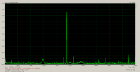
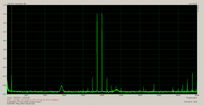
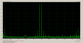
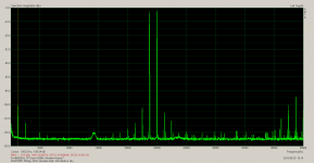
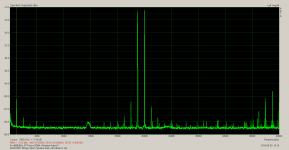
No VAS diode installed, 4R resistive load:
0.0022% IMD @ 10Vpp @4R
0.0021% IMD @ 20Vpp @4R
0.0020% IMD @ 40Vpp @4R
0.0022% IMD @ 60Vpp @4R
BR, Toni
IMD measurements
No VAS diode installed, 4R resistive load:
0.0022% IMD @ 10Vpp @4R
0.0021% IMD @ 20Vpp @4R
0.0020% IMD @ 40Vpp @4R
0.0022% IMD @ 60Vpp @4R
BR, Toni
Attachments

All really good results.
Thx! Some ppm better distortion figures are from your tip to actively drive the LTP cascode. Thx here too!
Hi Tony. How much of a negative impact does the vas diode make on the circuit performance.
Some ppm extra THD especially on higher loads @ higher frequencies.
You can omit the VAS diode, if you don't take care on best VAS sticking behaviour. The overall performance is very good even with VAS anti-saturation diode installed.
BR, Toni
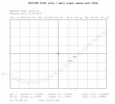
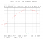
How did you get that sinewave+small square wave test signal?
What equipment, what method?
- sinus mixed with square wave generated with ltspice
- created a measure script for ltspice to get data points
- recalculate data with perl program and export to CSV
Have a look also at post #852.
BR, Toni
Attachments
Beyond my existing resources.
Owner of a soundcard capable of doing 96kHz or 192kHz wav material?
LTSpice can output a wav file ...
Code:
.wave "sinus.wav" 24 192000 x"x" is the output node. Simple edit the asc file some posts above, add the code line and change the simulation time to some seconds to generate a longer ".wav" sequence.
BR, Toni
Last edited:
I have two unworkable soundcards.
Both worked great until I downloaded a Members ASIO software/measurement file.
It corrupted something in the PC and I have never been able to undo the effects of those files.
I now only have windows integrated sound
You should have done a restauration of the OS, datas would had been preserved and new drivers/software removed with the system returning to a previous state.
If it was done a long time ago it s likely that there s no more a restauration state that is older than the dubbious installation.
2stageEF 50W MOSFET - aka SA2015MT
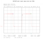
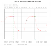
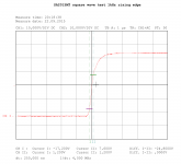
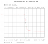
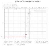
1kHz square wave test reloaded ...
1kHz square wave test reloaded ...
- IPS filter in situ
- VAS diode in situ
- OCP disabled
- 8R resistive load
Attachments
If you refer back to my post I linked to earlier, a lot of degeneration really isn't necessary and isn't really helpful unless your degeneration is matched, and even then it's questionable. LTPs benefit from matching but not THAT much, especially if the rest of your circuit produces significant H2. If you really want that level of matching, you will not get it by obsessing over matching; you should use trimmers instead.
Furthermore, large degeneration bootstraps Cbe and can slow down the transistor. The BC5x0C have reasonably small Cbe, but not the 2N5401's that people always try to use here.
I think a distinction could be made between common-mode degeneration and differential-mode degeneration. LTP degeneration is differential. CM degeneration is common. The difference is that LTP degeneration will influence harmonic profile while nominally, CM degeneration will not.
Different purposes can require different standards of degeneration. Slone chose the 50mV figure specifically for current mirrors, because is it large enough to swamp the differences in BJTs, but not larger than it needs to be.
For other degenerations, such as an EF output stage or an LTP, the needs are different. For an EF, there is the Oliver null point, above or below which you get more Gm distortion. For LTPs, it's usually a question of stability and slew rate. Degeneration also changes the harmonic profile, and I've heard 200mV is preferred by some designers in places where it affects the sound.
For a sense of scale, BJTs tend to have an emitter impedance of .033/Iq. So if we set degeneration to 33mV, our resistor matches the emitter impedance. At 200mV, the resistor is 6 times the emitter impedance. Whether degeneration is above or below 33mV determines whether the stage's Gm is mostly logarithmic or linear.
.033/Iq or R = 0.26/Iq. http://www.diyaudio.com/forums/solid-state/237176-cm-degeneration-resistor-noise-2.html#post4483386 or re = 25/Ic i am confused now , what's the correct way to determine re ? Current Sources, Sinks and Mirrors in Audio
Last edited:
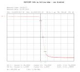
... attached 4R resistive load measurements.
THD+N measurements of output power above 120W@4R where not always possible due to current limiter of regulated power supply.
Right picture views current consumption on 10kHz / 140W / 4R output power test. Total power delivered by power supply ~ 240W
BR, Toni
I need more power supplies... yours look good. What is the make and model of them.
-RNM
I need more power supplies... yours look good. What is the make and model of them.
-RNM
Manufacturer: Mastech Power Supply - Variable DC Power Supply
Model: HY3005D-5
Output: 2 x 30V / 5A
BR, Toni
2stageEF 50W MOSFET - aka SA2015MT / BIAS Generator reloaded
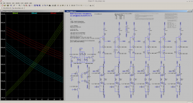
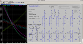
Have done some bias generator simulations to better understand what happens when
Real life measured:
Bias current is stable within < 5% from 24 degree to 60 degree heatsink temperature.
Bias current increases linear with power supply voltage from 35V to 50V.
BR, Toni
Have done some bias generator simulations to better understand what happens when
- power supply voltage increases from 35 - 50V
- heat sink temperature increases 0 - 66 degree
- case inner temperature increases when heat sink gets hotter
Real life measured:
Bias current is stable within < 5% from 24 degree to 60 degree heatsink temperature.
Bias current increases linear with power supply voltage from 35V to 50V.
BR, Toni
Attachments
- Home
- Amplifiers
- Solid State
- 2stageEF high performance class AB power amp / 200W8R / 400W4R