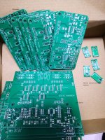
@dddac I am a middle-aged technical Chinese cabbage. Draw your own PCB according to the schematic (dddac1794pbt_nos_ver51.pdf) provided by you. As I read more, I have a question to ask the original poster. How to realize PCM1794 mono I/V conversion (without transformer version). Thank you very much! (I am not an electronic distributor, I am purely self-playing. Of course, I do not rule out selling redundant boards online. I only sell spare parts instead of finished boards. I will contact you for the sale)Thank you!
Attachments
Last edited:
What you do privately is fine - I allow that explicitly : "For DIY only"
by selling these boards you would be infringing my IP and copyright and I WILL take appropriate action.
This is quite bold what you state (not ruling out selling the boards) also posting it on my thread....
If see you are clever enough to draw your own boards, I am sure you can read datasheets and find out for your self what the answer to your question is
I have no interest in helping people who are stabbing my back and then ask for further support?
YES this pisses me off (and that is the first time in my many years on DIY forum....)
.
by selling these boards you would be infringing my IP and copyright and I WILL take appropriate action.
This is quite bold what you state (not ruling out selling the boards) also posting it on my thread....
If see you are clever enough to draw your own boards, I am sure you can read datasheets and find out for your self what the answer to your question is
I have no interest in helping people who are stabbing my back and then ask for further support?
YES this pisses me off
(and that is the first time in my many years on DIY forum....).
Last edited:
Thank you! Your response. What I mean is, if I can do a good job, keeping 4 more boards will be of no use. Others are willing to try and give it to him free of charge. If they don't want to find some components, maybe I will provide some, that's it. Since you do not agree, do it according to your wishes. Not much explanation, the more it gets darker.
Last edited:
DDDAC Power Supply
I just posted a new blog on my power supply:
Link to blog
The basic DDDAC kit is laid out to be a 1A max power supply. But is that really the max you can get out of this? And... are there other tweaks? How does this PSU actually work? Often heard: can I make a 2A or 3A PSU out of it?
This blog will try to answer those questions and will give some good guidance of the electronic background and deliver a few tweaks for everyone who wants to beef it up or experiment with the sound quality....
Great post, perfect timing for me!
Inserting the choke is an interesting tweak that I didn't think of yet. Am I correct that when you used the fuse holder to connect the choke (+ resistor), you didn't have a fuse anymore? I have learned the hard way that fuses can be a good thing to have. I guess I'll consider to cut a trace on the PCB and to insert the choke there instead of ditching the fuse.
Oh, and just for reference: I measured the current needed for the DDDAC mainboard + 8 x TENT DAC boards running at 12 VDC: at idle, the current is about 1.6 A and it goes up to 1.75 A when running at 192 kHz sampling rate.
Good for you timing was right...
Fuse, I would never recommend to refrain from safety of course. It is easy to add a fuse again in series. Point was that with the added resistance, there is less immediate problem and damage at an overload.
But... you are simply right of course
And thanks for the confirmation of the power consumption
I am trying to find out, how many clock bits the PCM1794 needs to pass the digital data to analog voltage after the WRCK(LRCK) loaded the data? The datasheet speaks nothing about it, maybe since all these years, you did notice about it. All the datasheet says, the WRCK must be operated 8× or 4× the desired sampled frequency fs. The duty cycle of LRCK must be 50% +/-2bit clock.
Last edited:
I guess I'll consider to cut a trace on the PCB and to insert the choke there...
Or maybe easier and no need to cut a trace: just remove R2 from the PCB (the big 0.1 Ohm / 5 W part connecting to the fuse) and install the choke in place of R2.
I am trying to find out, how many clock bits the PCM1794 needs to pass the digital data to analog voltage after the WRCK(LRCK) loaded the data? The datasheet speaks nothing about it, maybe since all these years, you did notice about it. All the datasheet says, the WRCK must be operated 8× or 4× the desired sampled frequency fs. The duty cycle of LRCK must be 50% +/-2bit clock.
You are mixing up things. The DDDAC works with no digital filter and the MCK is the same as the BCK in my design. The word clock or L/R clock is ONLY used to shift the bits into the serial resister. With the master clock the mash converter is being clocked, so in my case the BCK is the most important clock signal
8x or 4x the sample frequency has nothing to do with my implementation
Doede, I was thinking a bit more about the choke tweak you described in your blog.
In the example of your blog, you wrote that (without the choke) the delta voltage across the regulator was about 7 V. For proper operation, the regulator needs a delta of 5.6 V or more. With 7 V, you're well withing the "good" range.
Now, you added the choke (0.19 Ohm DC resistance) and an additional 1 Ohm resistor to attenuate the oscillation of the CLC filter. At 2 A, the choke + resistor will drop about 2.4 V. The new delta voltage for the regulator therefore ends up at 7 V - 2.4 V = 4.6 V, which is LESS than the 5.6 V minimum required for the regulator. Did you look into this?
If I got this right, I guess it might be better to use a CLC filter with a lower DC voltage drop. The trick will be to figure out the right combination of the L value, DC resistance and the size of the second capacitor in order to keep the DC voltage drop low, while avoiding oscillaton of the CLC.
All I want to know how many BCK it needs to pass the digital data to analog after the WRCK(LRCK) did fall. If you don't know don't answer, I'll understand.You are mixing up things. The DDDAC works with no digital filter and the MCK is the same as the BCK in my design. The word clock or L/R clock is ONLY used to shift the bits into the serial resister. With the master clock the mash converter is being clocked, so in my case the BCK is the most important clock signal
8x or 4x the sample frequency has nothing to do with my implementation
Last edited:
.... but i am not sure if it's worth it. I generally find there is limited hi-def material around...
I have > 10k high-res tracks and Qobuz has also a lot....
Doede, I was thinking a bit more about the choke tweak you described in your blog.
In the example of your blog, you wrote that (without the choke) the delta voltage across the regulator was about 7 V. For proper operation, the regulator needs a delta of 5.6 V or more. With 7 V, you're well withing the "good" range.
Now, you added the choke (0.19 Ohm DC resistance) and an additional 1 Ohm resistor to attenuate the oscillation of the CLC filter. At 2 A, the choke + resistor will drop about 2.4 V. The new delta voltage for the regulator therefore ends up at 7 V - 2.4 V = 4.6 V, which is LESS than the 5.6 V minimum required for the regulator. Did you look into this?
If I got this right, I guess it might be better to use a CLC filter with a lower DC voltage drop. The trick will be to figure out the right combination of the L value, DC resistance and the size of the second capacitor in order to keep the DC voltage drop low, while avoiding oscillaton of the CLC.
Correct, I used the choke only for 1A usage (4 decks). as you see in the graph there is still 20V DC at 1A with the 120VA. and you rightly interprate, that vor a 2 A version you want maybe a lower drop and also a bigger transformer, so the voltage would not drop so much....
I will add in the conclusions, that the high power and choke are not becesarilly going toherther without extra thoughts (like you did
)still with 2A there will be enough DC voltage for just 12 Volt (I measured 17,5V - 5,5 will still leave room for 12 Volt or so) I edited it as today mains voltage is a bit low - you need to have some buffer there as well ;-)
Last edited:
Just checked it with my beefed-up power supply:
- Transformer: 2 x 15 VAC, 120 VA
- C1 = 10'000 uF
- Ohmite FA-T220-64E heatsink on TIP122
- R2 and C3 as original (0.1 Ohm and 4'700 uF)
The output voltage was set to about 12.1 V, load was 5.5 Ohm, giving a current of 2.2 A (the target current for my DDDAC would be more like 1.8 A, so there is a bit of headroom).
The voltage across C1 was about 19.7 V. Dropout across the CRC was 0.1 Ohm x 2.2 A = 0.22 V. The dropout voltage across the regulator was therefore 19.7 V - 0.22 V - 12.1 V = 7.38 V. More than enough!
If 5.6 V dropout is the limit, the voltage drop across the CRC (or CLC) could be as much as 19.7 V - 12.1 V - 5.6 V = 2 V, corresponding to a total DC resistance in the CRC / CLC of 2 V / 2.2 A = 0.9 Ohm.
The next step is to play with PSUD to figure out an (almost) stable CLC configuration with a DCR = 0.9 Ohm. How much oscillation is allowed?
Hi Doede
Sorry, yet another question on your blog post regarding the chokes...
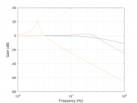
Looking at your TINA model plot with the filter gain functions for different choke values (10 mH, 1 H, 0 mH), both the 10 mH and 1 H curves show a little peak (ringing), and the peaks are about the same amplitude (about +2 dB). In the description of the plot you wrote that both curves were calculated using the same DC resistance, and the text does not say anything about the capacitance values, so I guess you also used the same C values. If so, the 1 H curve should have MUCH more ringing, i.e., the peak should be a lot higher (see my curves in the attachment for L = 0, 10 mH and 1 H with R = 1.2 Ohm and second C = 4700 uF). So I wonder what's actually in your plot. Can you shine some light on this?
To increase the attenuation of the filter, I believe it would be better to increase the value of the second cap rather than the choke.
Sorry, yet another question on your blog post regarding the chokes...
Looking at your TINA model plot with the filter gain functions for different choke values (10 mH, 1 H, 0 mH), both the 10 mH and 1 H curves show a little peak (ringing), and the peaks are about the same amplitude (about +2 dB). In the description of the plot you wrote that both curves were calculated using the same DC resistance, and the text does not say anything about the capacitance values, so I guess you also used the same C values. If so, the 1 H curve should have MUCH more ringing, i.e., the peak should be a lot higher (see my curves in the attachment for L = 0, 10 mH and 1 H with R = 1.2 Ohm and second C = 4700 uF). So I wonder what's actually in your plot. Can you shine some light on this?
To increase the attenuation of the filter, I believe it would be better to increase the value of the second cap rather than the choke.
Attachments
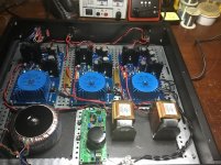
And... you can't just leave us hanging like that...Inspired by Doede. I installed one Lundahl 1694 choke on each 5v psu’s, which is feeding two 5v Ultra capacitor boards connected in series to get 10v for dddac mainboard with 4 dac boards.
- Home
- Source & Line
- Digital Line Level
- A NOS 192/24 DAC with the PCM1794 (and WaveIO USB input)