JohnnoG.
Looking forward to testing your new material.
nothing is guaranteed , but I am sometimes surprised by good sounding panels.
the low quality ply for instance ,surprised me, it doesn't sound like a ply ?
It was all I had lying around that matched the art panel size I needed.
so i was not expecting much.
But it seemed to work well with the art panel with the benefit of gaining quite a few db.
I can now play the panel much louder without the exciter heating up .
I like win win situations.
The only down side is there is more exciter noise problems , being transferred to the panel.
Applying the weights seem to sort most of that out ,which was good.
But hopefully using some of my techniques should eliminate this problem totally ?
It's not easy trying to predict the sound of a panel, or how it will react to changes you make to it.
I'll post a picture of how much the panel bends on its short width.
Steve.
Christian,
With regard to the form factor A, this relates to other papers Ive read, which confirm that (within limits) a longer panel gives higher SPL at low frequency, because below fc you only have edge/corner modes. Thus more edge length implies more greater SPL. Supported with anecdotal evidence like Burntcoil's 'tall blondes'. In addition, a tall panel confers other benefits like a more even radial dispersion and less comb filtering. So in my mind, a higher vertical aspect ratio is on my design checklist. Im thinking perhaps 3:1 eg 1200 x 400. Also looks better as a speaker!
No, of course. I don't meant that a high R would guarantee a good impulse response necessarily. Just that a high radiative efficiency works in the direction of a good impulse response, because kinetic energy converted to sound works just like frictional damping. And expressing R in terms of radiative damping gives us this insight.For now, I won't link this radiative damping (or efficiency) to the impulse response.
With regard to the form factor A, this relates to other papers Ive read, which confirm that (within limits) a longer panel gives higher SPL at low frequency, because below fc you only have edge/corner modes. Thus more edge length implies more greater SPL. Supported with anecdotal evidence like Burntcoil's 'tall blondes'. In addition, a tall panel confers other benefits like a more even radial dispersion and less comb filtering. So in my mind, a higher vertical aspect ratio is on my design checklist. Im thinking perhaps 3:1 eg 1200 x 400. Also looks better as a speaker!
I think Christian explained it well. In my understanding, the higher the aspect ratio, the higher the SPL at low frequency.Hi pway - I'd like to think that, as I prefer panels about 3:1 but for low Fo you need low A in that formula -> @1:1 the fractional part = 2, and @ 4:1 it equals 4.25. So worse not better.
Makes sense to me for isotropic plates as the skinny side stiffness predominates (depending on support conditions). However, in real life, natural timber and plywood are anisotropic which is of fundamental importance to the behaviour/performance of rectangular panels. Balancing lateral and longitudinal stiffnesses with aspect ratios is a goal for me.
Eucy
We agree that 3:1 might be a good aspect ratio. Ive only so far tested 2:1 but I take your experience as further supporting evidence!
pway,because below fc you only have edge/corner modes.
What do you mean by this? What is an "edge" or "corner" mode? Do you mean modes for which the edges or corners have the greatest displacement?
I don't know for sure, but I'm assuming that the relations you copied from the soundboard thesis are referring to simply supported and/or clamped plates, for which there would be no such "edge" or "corner" modes, since the edges are constrained. But perhaps that's not what you mean. Can you clarify?
Eric
I'm leaning somewhere between 3.5:1 and 4:1, but it depends on the degree of anisotropy of the moduli.I think Christian explained it well. In my understanding, the higher the aspect ratio, the higher the SPL at low frequency.
We agree that 3:1 might be a good aspect ratio. Ive only so far tested 2:1 but I take your experience as further supporting evidence!
Eric
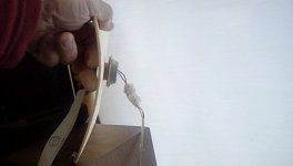
As can be seen in the photo, the panel bends easily on its short surface , but not so easily on its length.
what it would sound like the other way round ,I have no idea.
but this panel material works very well ,sound wise .
I need to visit my local vegetable market and pick up a few more crates 😁
Building panels that sound good is easy, trying to explain how they work and how to control them is another thing.
In the hitchhikers guide to the galaxy they found the perfect number , the answer to everything, but then realised they did not know what the question was ?
I think this forum is going down the same road ?
Steve.
Attachments
The theory says that for an infinite undamped plate, the far-field sound radiated at frequencies below fc is exactly zero. One way of explaining this is due to 'short-circuiting' of adjacent high and low pressure areas. Another way of saying the same thing (from solving the wave equation) is that there is a 'evanescent' wave near the plate, but it decays exponentially with distance from the plate. Here is an animation of the effect https://www.acs.psu.edu/drussell/Demos/EvanescentWaves/EvanescentWaves.htmlpway,
What do you mean by this? What is an "edge" or "corner" mode? Do you mean modes for which the edges or corners have the greatest displacement?
I don't know for sure, but I'm assuming that the relations you copied from the soundboard thesis are referring to simply supported and/or clamped plates, for which there would be no such "edge" or "corner" modes, since the edges are constrained. But perhaps that's not what you mean. Can you clarify?
Eric
For a finite plate, the radiated sound is not zero, because there are un-cancelled portions remaining at the edges and corners of the plate. These are the so-called edge and corner modes, which are the source of sound for panels when f<fc. They occur in all supporting conditions, clamped or otherwise. They are often mentioned in the literature, including the one I last referenced https://www.researchgate.net/publication/272518312_Radiation_efficiency_of_damped_plates. (Well, actually they explain in a similar fashion why a damped infinite panel has non-zero efficiency).
Agreed for both.Christian,
No, of course. I don't meant that a high R would guarantee a good impulse response necessarily. Just that a high radiative efficiency works in the direction of a good impulse response, because kinetic energy converted to sound works just like frictional damping. And expressing R in terms of radiative damping gives us this insight.
With regard to the form factor A, this relates to other papers Ive read, which confirm that (within limits) a longer panel gives higher SPL at low frequency, because below fc you only have edge/corner modes. Thus more edge length implies more greater SPL. Supported with anecdotal evidence like Burntcoil's 'tall blondes'. In addition, a tall panel confers other benefits like a more even radial dispersion and less comb filtering. So in my mind, a higher vertical aspect ratio is on my design checklist. Im thinking perhaps 3:1 eg 1200 x 400. Also looks better as a speaker!
Many posts before are about "which material with a good efficiency (=R)".
I don't have in mind posts saying a high aspect ratio is a problem. At the opposite we are collecting elements, theory and realizations in favor of high aspect ratio.
About material, I don't know where you are in the reading of the posts of this very very long thread... you may have a look to #4656 where I proposed to test the panel against spectral contamination which is a way to see the non linearity of the panel (like intermodulation distortion). I think it is a criteria in addition of the "R" to have a material classification. I haven't search for a metric neither the limit of audibility of distortion.
Christian
Hello Steve,As can be seen in the photo, the panel bends easily on its short surface , but not so easily on its length.
what it would sound like the other way round ,I have no idea.
but this panel material works very well ,sound wise .
I need to visit my local vegetable market and pick up a few more crates 😁
Building panels that sound good is easy, trying to explain how they work and how to control them is another thing.
In the hitchhikers guide to the galaxy they found the perfect number , the answer to everything, but then realised they did not know what the question was ?
I think this forum is going down the same road ?
Steve.
I think I stopped reading the "Hitchhiker's guide..." before that chapter but I saw that on Youtube. I hope we will stay practical enough not to go in this way! I am confident. Seeing the length of this thread and the lack of guidelines, I am in favor to continue this way.
And the answer is "42"... but what was your question?

Happy crate hunting... I am thinking to ask for polystyrene at my fishmonger (really! it is not a joke)
By the way I am happy you find quality in this plywood. I think it is close to poplar.
This morning I had a top of box (similar to a crate)... The difference of stiffness in both direction is really important... I don't know really the consequences but probably the aspect ratio as no meaning then. We should think about the dimension in low stiffness direction multiplied by the ratio of the stiffness (high stiffness on low stiffness).
Christian
Got that. I've shared that link myself, mainly trying to show how making measurements too close to the panel can give you a false sense of your panel's low frequency output. Close mic-ing is great for examining modal shapes, and linking modal shapes and frequencies, but not so great for frequency response characterization.The theory says that for an infinite undamped plate, the far-field sound radiated at frequencies below fc is exactly zero. One way of explaining this is due to 'short-circuiting' of adjacent high and low pressure areas. Another way of saying the same thing (from solving the wave equation) is that there is a 'evanescent' wave near the plate, but it decays exponentially with distance from the plate. Here is an animation of the effect https://www.acs.psu.edu/drussell/Demos/EvanescentWaves/EvanescentWaves.html
Eric
I read the same but this something I don't understand (Maybe I am in a wrong paradigm).The theory says that for an infinite undamped plate, the far-field sound radiated at frequencies below fc is exactly zero. One way of explaining this is due to 'short-circuiting' of adjacent high and low pressure areas. Another way of saying the same thing (from solving the wave equation) is that there is a 'evanescent' wave near the plate, but it decays exponentially with distance from the plate. Here is an animation of the effect https://www.acs.psu.edu/drussell/Demos/EvanescentWaves/EvanescentWaves.html
For a finite plate, the radiated sound is not zero, because there are un-cancelled portions remaining at the edges and corners of the plate. These are the so-called edge and corner modes, which are the source of sound for panels when f<fc. They occur in all supporting conditions, clamped or otherwise. They are often mentioned in the literature, including the one I last referenced https://www.researchgate.net/publication/272518312_Radiation_efficiency_of_damped_plates. (Well, actually they explain in a similar fashion why a damped infinite panel has non-zero efficiency).
When does the infinite start? 4.2m, 42m, 42km? Sorry I am still in the "Hitchhiker's guide...". Joke aside, I would really like to put an exciter at the biggest plywood panel I could find at the DIY store. Not really a priority in words of money, time and space... But really a curiosity.
I remember a post of a DIY builder, I don't remember if it is here or in the Audiocircle thread explaining he moved to a country (Madagascar?) where he installed very large panels and he was happy with. Even if we don't know the performance, some sound was produced.
So where does infinite start?
Christian
Okay, so by "edge and corner modes" you did not mean the flapping edges and corners of a free panel, but rather something else.For a finite plate, the radiated sound is not zero, because there are un-cancelled portions remaining at the edges and corners of the plate. These are the so-called edge and corner modes, which are the source of sound for panels when f<fc. They occur in all supporting conditions, clamped or otherwise. They are often mentioned in the literature, including the one I last referenced https://www.researchgate.net/publication/272518312_Radiation_efficiency_of_damped_plates. (Well, actually they explain in a similar fashion why a damped infinite panel has non-zero efficiency).
That is a great link by the way. And it references a lot of the seminal work in this area, which reminds me I have some reading to do!
But I'm still not following what you mean by edge and corner modes. I skimmed the article twice but still didn't see it referenced (although I guess you saw that too). Is there another paper that talks about edge and corner modes? I don't ever recall seeing that terminology, and I'm still confused what they are.
The sources I have found mainly talk about how, below fc, the modes with the highest radiation efficiency are the odd, odd modes. I have always assumed that the reason for this is that those modes (like the 1,3) shown below, are unbalanced and hence not fully "cancelling". That is it has two regions that are out of phase with the one other region.

While modes like this (1,4) on the other hand, have identical regions moving in opposite directions, and hence tend to cancel each other in the far field.

But this effect is not dependent on damping, so perhaps it is still not what you are talking about.
Eric
By which you mean that it's finally getting interesting, I'm sure.I think this forum is going down the same road ?
Eric
pway,
What I was talking about is this ( but better explained and shown):

https://www.sciencedirect.com/topics/engineering/radiation-efficiency
Eric
What I was talking about is this ( but better explained and shown):
https://www.sciencedirect.com/topics/engineering/radiation-efficiency
Eric
I can attest to this! Close mic-ing informs about the local behavior. The overall performance is the result of the combination of the behaviors of all the points. The next point is how to influence the design to minimize the dips (where the result of the combination is null).Got that. I've shared that link myself, mainly trying to show how making measurements too close to the panel can give you a false sense of your panel's low frequency output. Close mic-ing is great for examining modal shapes, and linking modal shapes and frequencies, but not so great for frequency response characterization.
Eric
Christian
Hello Eric,
Would it be possible to post some data of your composite CF Balsa CF planar speakers using REW Signal Generator and Scope ?
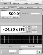
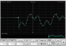
Here is what I see with my 3mm Colplast panel that is 900mm x 300mm and a 20W driver I was driving at 500Hz square wave 1Vrms and here is the oscope response of what the UM1k-1 microphone picked up. I would like to see the response of your speaker My panels are not clamped at the edges but are suspended by thin stainless wires at the top corners.
I think this shows the some of issues with panels with mass. It shows a slow rise and fall time with various oscillations which may be due to the reflected waves from edges of the panel. I be curious to see how your panel response is since if I am not mistaken is clamped and should be way stiffer with the CF than the polyethylene plastic that I have been using.
Again many thanks in advance
Would it be possible to post some data of your composite CF Balsa CF planar speakers using REW Signal Generator and Scope ?
Here is what I see with my 3mm Colplast panel that is 900mm x 300mm and a 20W driver I was driving at 500Hz square wave 1Vrms and here is the oscope response of what the UM1k-1 microphone picked up. I would like to see the response of your speaker My panels are not clamped at the edges but are suspended by thin stainless wires at the top corners.
I think this shows the some of issues with panels with mass. It shows a slow rise and fall time with various oscillations which may be due to the reflected waves from edges of the panel. I be curious to see how your panel response is since if I am not mistaken is clamped and should be way stiffer with the CF than the polyethylene plastic that I have been using.
Again many thanks in advance
Attachments
Tagis,Hello Eric,
Would it be possible to post some data of your composite CF Balsa CF planar speakers using REW Signal Generator and Scope ?
Here is what I see with my 3mm Colplast panel that is 900mm x 300mm and a 20W driver I was driving at 500Hz square wave 1Vrms and here is the oscope response of what the UM1k-1 microphone picked up. I would like to see the response of your speaker My panels are not clamped at the edges but are suspended by thin stainless wires at the top corners.
I think this shows the some of issues with panels with mass. It shows a slow rise and fall time with various oscillations which may be due to the reflected waves from edges of the panel. I be curious to see how your panel response is since if I am not mistaken is clamped and should be way stiffer with the CF than the polyethylene plastic that I have been using.
Again many thanks in advance
I think I probably can. I've never used the scope function on REW (didn't even realize it was there!) so there may be some learning curve to it.
I have some other stuff I'm working on so may take a few days, so be patient.
My CF balsa panels are actually not mounted at the moment. But I have frames that fit that I can easily mount a panel to in a matter of a few minutes. It won't be "clamped" but would be attached to the frame around most of the perimeter with any one of several double sided foam tapes. It's more like "simple" (i.e. hinged) supports than clamped. Would you like me to choose a foam tape that has high damping, or low damping? Is the mic at 1 meter?
Eric
Hello TagisHello Eric,
Would it be possible to post some data of your composite CF Balsa CF planar speakers using REW Signal Generator and Scope ?
Here is what I see with my 3mm Colplast panel that is 900mm x 300mm and a 20W driver I was driving at 500Hz square wave 1Vrms and here is the oscope response of what the UM1k-1 microphone picked up. I would like to see the response of your speaker My panels are not clamped at the edges but are suspended by thin stainless wires at the top corners.
I think this shows the some of issues with panels with mass. It shows a slow rise and fall time with various oscillations which may be due to the reflected waves from edges of the panel. I be curious to see how your panel response is since if I am not mistaken is clamped and should be way stiffer with the CF than the polyethylene plastic that I have been using.
Again many thanks in advance
May I suggest another method... REW offers a spectrogram function that give a 3D view : SPL according to frequency and time. I use the wavelet option.
Below is the spectrogram of a "pure" pulse leading to a flat FR. You'll see in the box the settings.
After is the spectrogram of a completely free small EPS panel. See the "islands" that occur after time 1ms are I think the signature of too low damping, reflections at the edge.
@Veleric
Eric,
In the documents referenced in M Ege's thesis, there is this patent US3724312A about a foam body soundboard for piano. 2 points

Eric,
In the documents referenced in M Ege's thesis, there is this patent US3724312A about a foam body soundboard for piano. 2 points
- the same statement about the effect of ribs in a standard piano soundboard
- the ring shaped parts that link the 2 faces of the board where the bridge is connected to the soundboard to avoid the loss in high frequency due to the foam
- Home
- Loudspeakers
- Full Range
- A Study of DMLs as a Full Range Speaker