Hi pway,If I understand the design it also suffers from dramatic field leakage, and is even more non-linear because the force increases as the coil approaches the magnet. So it risks colliding.
Field leakage will certainly happen but providing their is sufficient field strength where the coil passes through the field I am not sure that’s a problem. To be tested.
On linearity it should be fine with two opposing magnets. As the coil moves away from one magnet the other coil is moving closer to its magnet. In this regard it is somewhat like an electrostatic panel and diaphragm. Clearance is also a matter of experimentation. It may be that these multiple demands cannot be met with acceptable efficiency but that’s the objective of experimentation.
Burnt
I used to own Magnapans... I'm right with you!!Radial Thoughts
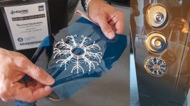
@Andre Bellwood, I had some thoughts in the same direction, mounting coils directly on the panels, but I came out in a different place. You can use flat coils mounted directly to the surface if you use radially magnetised ring magnets. To max out the field strength you can use two sets of coils and magnets on opposite sides which would flatten and intensify the magnetic field. You would have to invert the phase on one set of coils obvs. A manufacturer would be able to get custom ring magnets made up which is too expensive for DIY but you can sort off simulate the same effect using a radial array of bar magnets. Images attached.
I thought there were a number of benefits in that you can split the flat coils into several concentric coils allowing you to control inductance by summing in parallel/series to get the inductance you need which might help the top end performance. Coil heating would also be reduced as the coils are in open air and free to radiate and conduct away heat helping to extend performance limits. As my preference would be to use neodymium magnets there is also the benefit of getting iron out of the circuit reducing eddy current effects, although I am not sure if this is significant. Robustness and alignment tolerance will be much better as the displacement of coil to magnets by a few millimetre is no long a disaster, just a mild drop in performance.
One of the interesting questions for me is how you would treat the voice coil mass now it is directly attached to the panels and the effect this has on mechanical impedance and impulse transmission. This is all very theoretical at the moment, and predicated on being able to get a high enough B. Increasing L will be trivial. I expect there is something I have not thought of that will kill the idea, there usually is, but if I get anywhere I will report back to the group.
Burnt
Cons:
XMax determines BL.... High XMax = low BL. And vice-versa;
BL changes according to VC/Magnet distance during a cycle, hence increasing (2nd-harmonic?) distortion.
Pros:
No alignment problems.
No crud-in-the-pole-gap problems.
No coil former. = reduced Mms
Large contact area
....
https://jinluncicai.en.made-in-chin...ent-Neodymium-NdFeB-Magnet-with-List-226.html
https://hartai.en.made-in-china.com...l-Wireless-Charging-Coil-Inductance-Coil.html

Steve that certainly sounds like an experiment you should try.This setup is very similar to fig 5a in the parent Andre just posted.
I did mention some years back , bolting two exciters on opposite sides of my ply panels.
I never managed to get around to doing it, but thought it could be good for pro use.
Steve.
Burnt
I agree Andre, Magnepans approach occurred to me while thinking it through also. Jim Winey was a smart guy. That’s a promising combination of magnet and coil in your links as well.I used to own Magnapans... I'm right with you!!
Cons:
XMax determines BL.... High XMax = low BL. And vice-versa;
BL changes according to VC/Magnet distance during a cycle, hence increasing (2nd-harmonic?) distortion.
Pros:
No alignment problems.
No crud-in-the-pole-gap problems.
No coil former. = reduced Mms
Large contact area
....
https://jinluncicai.en.made-in-chin...ent-Neodymium-NdFeB-Magnet-with-List-226.html
https://hartai.en.made-in-china.com...l-Wireless-Charging-Coil-Inductance-Coil.html
Burnt
Jaxboy.
I did have a little listen to the canvas panel with the coffee whizzer on late last night, until 2am😵💫
The whizzer wasn't very up front and in your face which I liked.
But it had a lot of detail, and as I said before, life.
I thought of you and your hearing problems, and thought it could be a good free upgrade for you.
It gives more detail down to 1k or so, so it is not just a tweeter for above 10k.
I don't know if there is a smaller size than the 2cm deep coffee container, but the 2cm seems to work quite well.
The small cut down one I used didn't do so well.
Just a thought.
All the best .
Steve.
👍Quick sketch to check out issues...
Hello AndréI used to own Magnapans... I'm right with you!!
Cons:
XMax determines BL.... High XMax = low BL. And vice-versa;
BL changes according to VC/Magnet distance during a cycle, hence increasing (2nd-harmonic?) distortion.
Pros:
No alignment problems.
No crud-in-the-pole-gap problems.
No coil former. = reduced Mms
Large contact area
....
https://jinluncicai.en.made-in-chin...ent-Neodymium-NdFeB-Magnet-with-List-226.html
https://hartai.en.made-in-china.com...l-Wireless-Charging-Coil-Inductance-Coil.html
Which evidence a large contact area is a target?
What will be the bandwidth then?
Christian
Hi Chris!Hello André
Which evidence a large contact area is a target?
What will be the bandwidth then?
Christian
I'm going according to the EPS-with-polycarb disc that I was testing. It seems as-if a hard surface of a certain size might influence not just the FR, but the high end too.
I don't know if this agrees with the math or not?
You are very naughty 😉Steve that certainly sounds like an experiment you should try.
Burnt
I need another experiment like I need a hole in the head.
I could just glue a second exciter on the front of one of my 6ft rigid ply panels? Without the bolt?
And see what happens?
Joppe etches his own film coils, foils, for his panels , this could work , but only for light materials maybe?
The problem is you always have magnets in the way, especially if it is push pull.
Plus the mounting, housing?
“I could just glue a second exciter on the front of one of my 6ft rigid ply panels? Without the bolt?You are very naughty 😉
I need another experiment like I need a hole in the head.
I could just glue a second exciter on the front of one of my 6ft rigid ply panels? Without the bolt?
And see what happens?
Joppe etches his own film coils, foils, for his panels , this could work , but only for light materials maybe?
The problem is you always have magnets in the way, especially if it is push pull.
Plus the mounting, housing?
And see what happens?”
Excellent idea. I look forward to seeing the results.
Burnt
Noooooooooooooooo !!!!!!!“I could just glue a second exciter on the front of one of my 6ft rigid ply panels? Without the bolt?
And see what happens?”
Excellent idea. I look forward to seeing the results.
Burnt
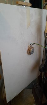
I found this old ply painted panel , it is covered in dust and cobwebs, I had been using it to stop drafts from the chimney.
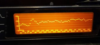
Anyway, I made some measurements on it with the coffee ☕ whizzer .
Very interesting , to me anyway.
Pic1 the panel
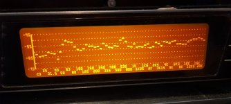
Pic2 panel only measurement
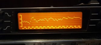
Pic3 with 2cm cw good increase in response above 2k.
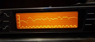
Pic4 with 3cm cw , surprisingly not as bad as expected, I think the bluetack is helping to damp the lower frequencies as well.
Pic5 I removed some of the bluetack from the 2cm cw and measured again.
The response not only seems smoother above 2k but also below?
I will have another listen tonight to see if I can hear any nasty colourations and such.
But nothing bad stands out so far?
I only have one 2 cm cw at the moment, I could cut a 3cm down a little to match, but the rim might be helping the sound?
Steve.
Ps , I should have mentioned the measurements were taken a 12inches distance.
Steve.
Anyway, I made some measurements on it with the coffee ☕ whizzer .
Very interesting , to me anyway.
Pic1 the panel
Pic2 panel only measurement
Pic3 with 2cm cw good increase in response above 2k.
Pic4 with 3cm cw , surprisingly not as bad as expected, I think the bluetack is helping to damp the lower frequencies as well.
Pic5 I removed some of the bluetack from the 2cm cw and measured again.
The response not only seems smoother above 2k but also below?
I will have another listen tonight to see if I can hear any nasty colourations and such.
But nothing bad stands out so far?
I only have one 2 cm cw at the moment, I could cut a 3cm down a little to match, but the rim might be helping the sound?
Steve.
Ps , I should have mentioned the measurements were taken a 12inches distance.
Steve.
Attachments
re: making exciters ...
Pure brainstorming follows. (Note, I have more curiosity about this than real knowledge.)
Could one adapt field coils to create exciters for DMLs?
DC powered electromagnets to drive a motor.
The magnetism in permanent magnets follows from aligned electron spin.
Moving electric charges in which the electron spins don’t all align generate magnetic fields in electromagnets.
Field coil driver’s flux field density remains constant whenever voice coils move in the motor’s gap.
Permanent magnets can experience sags in flux density.
Field coil motor strength determined by current and voltage, which stabilizes power delivery.
Generally built by hand.
@Hentai started a thread on this site back in 2012 although he focused on building a field coil driven cone.
Project Ryu - DIY Field Coil Loudspeaker
So, potentially:
lighter in weight
buildable by hand.
stable flux field density
Negatives you can't get much cheaper than commercially available exciters.
probably lots of other things.
any picture of field coil powering dml?re: making exciters ...
Pure brainstorming follows. (Note, I have more curiosity about this than real knowledge.)
Could one adapt field coils to create exciters for DMLs?
DC powered electromagnets to drive a motor.
The magnetism in permanent magnets follows from aligned electron spin.
Moving electric charges in which the electron spins don’t all align generate magnetic fields in electromagnets.
Field coil driver’s flux field density remains constant whenever voice coils move in the motor’s gap.
Permanent magnets can experience sags in flux density.
Field coil motor strength determined by current and voltage, which stabilizes power delivery.
Generally built by hand.
@Hentai started a thread on this site back in 2012 although he focused on building a field coil driven cone.
Project Ryu - DIY Field Coil Loudspeaker
So, potentially:
lighter in weightbuildable by hand.stable flux field densityNegatives
you can't get much cheaper than commercially available exciters.probably lots of other things.
None that I know.any picture of field coil powering dml?
This is the most advanced bmr driver in the industry. I will try to put voice coil trough the panel some day, phase plug is also good idea. https://www.infoaudio.pl/artykul/21...osc-glosnikow-na-przykladzie-flagowego-medeos
any picture of field coil powering dml?
As I said, maybe I just don't understand. I'm trying to imagine the field lines from the radial magnet. They come out of the edge at the outer circumference radially, then turn in toward the panel, then again radially in the opposite direction more-or-less parallel to the panel (this is the part you want to use I guess), then they curve back away from the panel, and finally re-enter radially in the same direction as they exited. Is this your mental model?Hi pway,
Field leakage will certainly happen but providing their is sufficient field strength where the coil passes through the field I am not sure that’s a problem. To be tested.
On linearity it should be fine with two opposing magnets. As the coil moves away from one magnet the other coil is moving closer to its magnet. In this regard it is somewhat like an electrostatic panel and diaphragm. Clearance is also a matter of experimentation. It may be that these multiple demands cannot be met with acceptable efficiency but that’s the objective of experimentation.
Burnt
- Home
- Loudspeakers
- Full Range
- A Study of DMLs as a Full Range Speaker