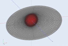
In the meantime I ran the analysis - is this it? ")
- Ouch, same mistake again, I forgot to switch the velocity to axial - so this is wrong... OK, once again.
- Ouch, same mistake again, I forgot to switch the velocity to axial - so this is wrong... OK, once again.
Attachments
Simulations for the axial dome motion - it's not much better
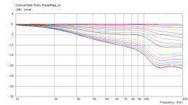
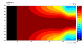
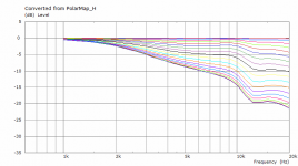
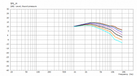
Raw horizontal polars (constant acceleration):

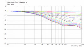
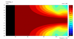
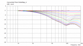
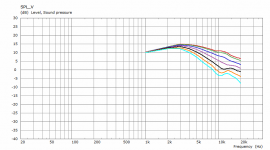
Vertical:

Attached also the normalized responses to 0 deg.
I'm really interested to see the measured data - how much are we off with this.
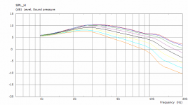
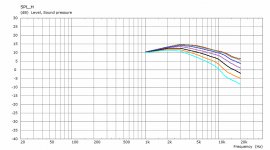
Raw horizontal polars (constant acceleration):
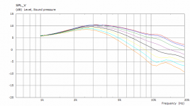
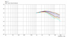
Vertical:
Attached also the normalized responses to 0 deg.
I'm really interested to see the measured data - how much are we off with this.
Attachments


You can set any step you need. This is for 0 - 60 / 10 for the raw polars ("SPL_H/V" charts). Polar maps are per 5 deg by default.
ABEC.SimType = 1 ; infinite baffle
ABEC.f1 = 1000 ; [Hz]
ABEC.f2 = 20000 ; [Hz]
ABEC.NumFrequencies = 20
ABEC.MeshFrequency = 1000 ; [Hz]
ABEC.Abscissa = 2 ; linear
ABEC.Polars.Dist = 1.5 ; mic distance - adjust this to your value [m]
ABEC.Polars.Step = 10 ; angular step [deg]
ABEC.Polars.Points = 7 ; # of polars
ABEC.Polars.Horizontal = 1
ABEC.Polars.Vertical = 1
ABEC.Polars.Diagonal = 0
ABEC.Polars.DiagonalInclination = 0.0
ABEC.Polars.PMapNorm = 10 ; polar map normalizing angle [deg]

I think the match is pretty good. There may still be differences due to the different radiating conditions. I work on finite baffles - that will be even closer.
BTW, this was calculated for 20 points only. Solved in 10 minutes.
ABEC.SimType = 1 ; infinite baffle
ABEC.f1 = 1000 ; [Hz]
ABEC.f2 = 20000 ; [Hz]
ABEC.NumFrequencies = 20
ABEC.MeshFrequency = 1000 ; [Hz]
ABEC.Abscissa = 2 ; linear
ABEC.Polars.Dist = 1.5 ; mic distance - adjust this to your value [m]
ABEC.Polars.Step = 10 ; angular step [deg]
ABEC.Polars.Points = 7 ; # of polars
ABEC.Polars.Horizontal = 1
ABEC.Polars.Vertical = 1
ABEC.Polars.Diagonal = 0
ABEC.Polars.DiagonalInclination = 0.0
ABEC.Polars.PMapNorm = 10 ; polar map normalizing angle [deg]
I think the match is pretty good. There may still be differences due to the different radiating conditions. I work on finite baffles - that will be even closer.
BTW, this was calculated for 20 points only. Solved in 10 minutes.
Attachments
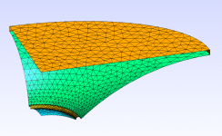
Looking more closely on your geometry, it seems that the vertical profile arc touches the baffle at slightly higher angle. When I checked my radiuses they were 74.6 and 25.5 mm, horizontally and vertically.
Maybe this will be a bit closer to what you have:
CircArc.TermAngle = 0.8 + 7*sin(p)^2
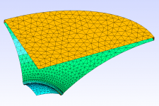
Now the radiuses are 73.9 and 30.5 mm. Updated STL attached.
Maybe this will be a bit closer to what you have:
CircArc.TermAngle = 0.8 + 7*sin(p)^2
Now the radiuses are 73.9 and 30.5 mm. Updated STL attached.
Attachments
Last edited:
Looking more closely on your geometry, it seems that the vertical profile arc touches the baffle at slightly higher angle. When I checked my radiuses they were 74.6 and 25.5 mm, horizontally and vertically.
Maybe this will be a bit closer to what you have:
CircArc.TermAngle = 0.8 + 7*sin(p)^2
Now the radiuses are 73.9 and 30.5 mm. Updated STL attached.
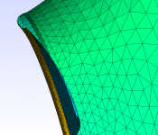
I'm not quite following, are the wall profile radiuses not 73.66 and 30.48 mm as I specified? Looking at the .cfg I see they are not even there, so some function with certain assumptions (tangent at baffle for example) must be calculating a best fit when given mouth size, throat size, depth, etc? Is there a way to direct code the radius?
If you think about it, it's not that easy - what's the radius on the diagonals and everywhere between? If you wanted to set the radii directly you would have to know this. I chose a different approach - you define the throat, the mouth outline (whatever that is) and the angle at which the arc should meet the baffle (=CircArc.TermAngle). The radii around the waveguide are simply calculated from that.
- Home
- Loudspeakers
- Multi-Way
- Acoustic Horn Design – The Easy Way (Ath4)