
Yeah, I think it could be approximated pretty well with what I have. It may also be interesting to try optimize for an impedance target, i.e. what shape would be the result.Pas de problème")

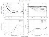
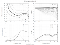
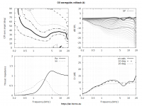
No rollback -
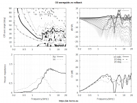
Not exactly state-of-the-art, that one... I wonder how these things measure:


Last edited:
But hey, if it costs xxxxxxxxxx dollars then it sounds good no matter what the measurement says!
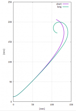
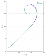
It is kind of amusing how small changes change the result so much. It looks like that any required parameters (throat size, next "way" woofer size, radiation pattern size) there is optimum shape that needs to be found out (or have you found some pattern?). Great work!
I wonder how much of a difference there is to perceived sound, for example between the ones in post #4481? I think they are small.
ps. pattern control must affect quite a lot to a perceived sound quality in home, since the simple horn without mouth termination seems to sound just fine. For example most of the commercial PA speakers (waveguides) don't consider this kind of thing at all. Most home made waveguides (multiple entry horns seem to be the most popular) are made from sheet stock and people like their qualities.
It is kind of amusing how small changes change the result so much. It looks like that any required parameters (throat size, next "way" woofer size, radiation pattern size) there is optimum shape that needs to be found out (or have you found some pattern?
). Great work!I wonder how much of a difference there is to perceived sound, for example between the ones in post #4481? I think they are small.
ps. pattern control must affect quite a lot to a perceived sound quality in home, since the simple horn without mouth termination seems to sound just fine. For example most of the commercial PA speakers (waveguides) don't consider this kind of thing at all. Most home made waveguides (multiple entry horns seem to be the most popular) are made from sheet stock and people like their qualities.
Last edited:
Remember the Beranek's Law?
"...if one selects his own components, builds his own enclosure, and is convinced he has made a wise choice of design, then his own loudspeaker sounds better to him than does anyone else's loudspeaker. In this case, the frequency response of the loudspeaker seems to play only a minor part in forming a person's opinion."
L.L. Beranek, Acoustics (McGraw-Hill, New York, 1954)
I would be able to add a model of a compression driver myself...
Where you get stuck creating the driver model ? Lumped element script ?
I can share my LE script. I have used FDD loudspeaker model (including semi-inductance and frequency dependendent damping (visco-elastic creep))
Scientific papers
Thiele Small Parameters
Actually, this is the same model used for impedance fitting in REW.
However, note, that you need to measure the driver impeance in vacuum to substract the air load (I have measured measured cp380m in vacuum if you need them).
The script consists of six main part:
1. description of constants
2. description of electrical part including semi-nductance model (Lpp and Rpp in my notation in the script)
3. Desctiption of the motor
4. Mechanical part including frequecny-dependent damping (w*Aes)
5. Membrane description includes all of the above parameters
6. and finaly part "RadImp" "binds" front and back side of the membrane to the BEM solving script
As far as I remember, I used the same parameter notation as used in REW
Code:
Def_Driving "Driving"
// Value={10^((-0+20)/20)} // -15dBV + 20dB amplifier
Value=0.22V IsRms

Def_Const
    {
Bl=12.36858;
Rdc=5.287;
dR=0.12022;
Leb1=72.89476e-6;
Le1=1.27858e-3;
Rss=5.36765;
Ksh=0.15487;
Mms=18.22018e-3; // air load substracted
Cms=433.08e-6;
Res=1489.57997;
Aes=2643.50998e-3;
SDd=0.0162;
dD=Sqrt(SDd/pi);
Rms=Bl*Bl/Res;
    }

 System  'S1'

//Electrical part
Impedance  'Ze'
      Node=1=2
      Z={
	  Rpp=Cos(3.1415926536/4)/(Ksh*w^0.5);
	  Lpp=Sin(3.1415926536/4)/(Ksh*w^-0.5);

		A=(Rss+Rpp)/(Rss*Rpp);
		B=(Le1+Lpp)/(w*Le1*Lpp);

		ReZblock=(Rdc+dR)+(A/(A^2+B^2));
		ImZblock= w*Leb1+(B/(A^2+B^2));

		Ze = ReZblock + j*ImZblock;}

// Motor
Gyrator 'G1' Node=2=0=3=0 Bl={Bl}

// Mechanical part
Impedance  'Zms'
Node=3=5
	Z={Ams = Bl*Bl/(w*Aes) ;}

//membrane
Membrane 'Membrane_din2' Node=5=0=1000=2000 DrvGroup=1001,1002
Cms={Cms} Mms={Mms} Rms={Rms}

// coupbling to the BEM
RadImp "RI1" Node=1000 DrvGroup=1001
RadImp "RI2" Node=2000 DrvGroup=1002
Last edited:
Thank you, much appreciated indeed. I think I don't need a model of a particular driver. Something generic and simplified should suffice for the comparisons for the time being.
Is it necessary to couple the rear side of the diaphragm to BEM? Could you show how does the mesh look like then? Could be the chamber behind the diaphragm simply modeled as a (lumped) compliance?
Is it necessary to couple the rear side of the diaphragm to BEM? Could you show how does the mesh look like then? Could be the chamber behind the diaphragm simply modeled as a (lumped) compliance?
Last edited:
upd. I noticed, that that latest version of REW uses more complex Ritter 3PC suspension model to model visco-elastic creep and there is no Aes parameters, so mechanical part of my LE script above should be updated according to the latest REW revision.
Actually yes, you can model the back side by a simple acoustic compliance element. Also you can write script similar to mine but without visco-elastic creep and semi-inductance. The script with a lumped box connected to the back side(front and back side is node 1000 and 2000, respectively) should look something like this (I have bolded the changes, but I have not tested the script, it only demonstrates general idea what you need to change and how to operate with lumped elements in ABEC)
Yes, you can use lumped phase plug. There is very informative manual of older Akabak version (its syntax is very similar to the Abecs one) how to do this (pp. 61-64).
Another approach how compression driver can be lumped was described by Kinoshita and Locanthi
AES E-Library >> Design of 48mm Beryllium Diaphragm Compression Driver
AES E-Library >> The Influence of Parasitic Resonances on Compression Driver Loudspeaker Performance
If you're not in a hurry, I can prepare in my spare time Abec3 script with the lumped driver model.
Is it necessary to couple the rear side of the diaphragm to BEM? Could you show how does the mesh look like then? Could be the chamber behind the diaphragm simply modeled as a (lumped) compliance?
Actually yes, you can model the back side by a simple acoustic compliance element. Also you can write script similar to mine but without visco-elastic creep and semi-inductance. The script with a lumped box connected to the back side(front and back side is node 1000 and 2000, respectively) should look something like this (I have bolded the changes, but I have not tested the script, it only demonstrates general idea what you need to change and how to operate with lumped elements in ABEC)
Code:
Def_Driving "Driving"
// Value={10^((-0+20)/20)} // -15dBV + 20dB amplifier
Value=0.22V IsRms

Def_Const
    {
Bl=12.36858;
Rdc=5.287;

dR=0.12022;
Leb1=72.89476e-6;
Le1=1.27858e-3;
Rss=5.36765;
Ksh=0.15487;

Mms=18.22018e-3; // air load substracted
Cms=433.08e-6;

Res=1489.57997;
Aes=2643.50998e-3;

SDd=0.0162;
dD=Sqrt(SDd/pi);
Rms=Bl*Bl/Res;
    }

 System  'S1'

//Electrical part
Impedance  'Ze'
      Node=1=2
      Z={
	  Rpp=Cos(3.1415926536/4)/(Ksh*w^0.5);
	  Lpp=Sin(3.1415926536/4)/(Ksh*w^-0.5);

		A=(Rss+Rpp)/(Rss*Rpp);
		B=(Le1+Lpp)/(w*Le1*Lpp);

		ReZblock=(Rdc+dR)+(A/(A^2+B^2));
		ImZblock= w*Leb1+(B/(A^2+B^2));

		Ze = ReZblock + j*ImZblock;}

// Motor
Gyrator 'G1' Node=2=0=3=0 Bl={Bl}

// Mechanical part
Impedance  'Zms'
Node=3=5
	Z={Ams = Bl*Bl/(w*Aes) ;}

[B]AcouCompliance  'Ca1'    Node=2000
    Ca={ Vb=100e-3; roh=1.2; c=344;  Vb/(roh*sqr(c)) }	[/B]

//Enclosure 'E1' //you can also use Enclosure element instead of AcouCompliance
//    Node=2000
//    Vb=100L

//membrane
Membrane 'Membrane_din2' Node=5=0=1000=2000 [B]DrvGroup=1001[/B]
Cms={Cms} Mms={Mms} Rms={Rms}

// coupbling to the BEM
RadImp "RI1" Node=1000 DrvGroup=1001
[B]RadImp "RI2" Node=2000 Def='Ca1'[/B]
It's not clear to me how you model the phase plug. Is it modeled completely via BEM?
- My aim at the moment was to reduce the phase plug model as feasible - just as a compression ratio (a transformer), maybe? Is that possible?
Yes, you can use lumped phase plug. There is very informative manual of older Akabak version (its syntax is very similar to the Abecs one) how to do this (pp. 61-64).
Another approach how compression driver can be lumped was described by Kinoshita and Locanthi
AES E-Library >> Design of 48mm Beryllium Diaphragm Compression Driver
AES E-Library >> The Influence of Parasitic Resonances on Compression Driver Loudspeaker Performance
If you're not in a hurry, I can prepare in my spare time Abec3 script with the lumped driver model.
Attachments
Last edited:
- Home
- Loudspeakers
- Multi-Way
- Acoustic Horn Design – The Easy Way (Ath4)