Thinking about the "LWDI" a little more, one wouldn't want to go too much far off-axis because even a highly directional device could have this average DI pretty flat after all. So I should probably take something closer to the axis. When this is flat (or close to the target), the rest should be no worse, hopefully.
I did and I still wait for your another post saying you increased the tilt even more since then")
I haven't felt any need to do that so far. It's possible that my use of upmixing (or "ambience channels", if you prefer) is a contributing factor. Or maybe I just like treble more than you
.one wouldn't want to go too much far off-axis because even a highly directional device could have this average DI pretty flat after all.
That's true. The averaging window may have to be tailored based on the target beamwidth.
This ain't bad.
Your example is perfect proof of my claim that "cutoff" doesn't matter. Look at the impedance and see how even at about .1 the waveguide still have a lot of usable output - at least an octave below the so-called cutoff.
Unless the data is normalized, then we can't tell. (Which is why I never normalize the data.)
Last edited:
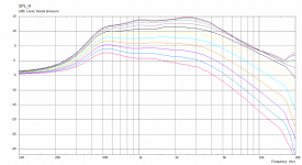
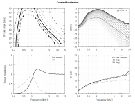
That data is definitely normalized. Here's some non-normalized data for a different device driven by a constant acceleration source:


I don't know how one defines "cutoff" for this kind of device, but the predicted SPL starts to drop significantly below 500Hz. The radiation impedance at 500Hz is very low at 0.027+0.229j.
I don't know how one defines "cutoff" for this kind of device, but the predicted SPL starts to drop significantly below 500Hz. The radiation impedance at 500Hz is very low at 0.027+0.229j.
Attachments
Last edited:
This simulation, like virtually all presented in this thread so far, uses an ideal constant acceleration element at the throat boundary as a source, i.e. is in fact ignoring the real loading properties of the device (at least as I understand the matter). I'm not sure how meaningful this is in that regard.
- As long as we are interested in radiation patterns only, this is perfectly fine because the pattern is invariant, but for the "loading" aspects, I would think we should use a driver model as well. Shouldn't we?
- As long as we are interested in radiation patterns only, this is perfectly fine because the pattern is invariant, but for the "loading" aspects, I would think we should use a driver model as well. Shouldn't we?
Last edited:
What I meant is that even a highly beaming device (i.e. one with steeply rising on-axis DI) will have more or less flat DI at some angle off-axis.That's true. The averaging window may have to be tailored based on the target beamwidth.
- In reality even the so called "flat DI" device will have the DI flat only in some off-axis angle range.
Last edited:
This simulation, like virtually all presented in this thread so far, uses an ideal constant acceleration element at the throat boundary as a source...
I would think we should use a driver model as well. Shouldn't we?
Absolutely.
My first reaction was similar to this
More than I expected too, I started to wonder what the mechanism could be- how could the response only drop substantially so far below the frequency that the load drops off?Makes my point even more than I expected.
I arrived at similar doubts to you because I still can't see it.
So if a proper driver simulation is done and confirms the result then there will be no reasonable doubt and I (and others) will have to rethink.
And that will be at least as educational as the opposite result.
Best wishes
David
Last edited:
Why not use constant velocity (p=v*z) ?! I always use in my simulations constant velocity and I have not observed any phenomena related to radiation below "cut-off" frequency.
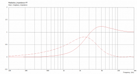
The picture below demonstrates SPL at 1.3m and radiation impedance of the biradial horn (designed by well known Japan corporation) that I simulate in ABEC3 under constant velocity condition. Radiation below the "cut-off" falls drastically.

The picture below demonstrates SPL at 1.3m and radiation impedance of the biradial horn (designed by well known Japan corporation) that I simulate in ABEC3 under constant velocity condition. Radiation below the "cut-off" falls drastically.
Does it really make a difference when we don't consider a driver model?Why not use constant velocity (p=v*z) ?!
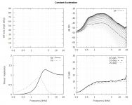
Constant acceleration (contours out of range):
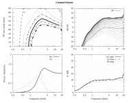
Constant velocity:
Attachments
these are oblate spheroid based curves,no?
No, this is some kind of hyperbolic curves.
Does it really make a difference when we don't consider a driver model?
I don't think that there is a differece if you mean optimisation of a horn directivity and acoustic loading.
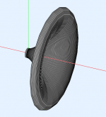
Finally, some random, beaming piece of junk
In practice this may not be so bad.
- Home
- Loudspeakers
- Multi-Way
- Acoustic Horn Design – The Easy Way (Ath4)