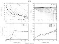
I don't know how one defines "cutoff" for this kind of device, but the predicted SPL starts to drop significantly below 500Hz. The radiation impedance at 500Hz is very low at 0.027+0.229j.
There's no hard cutoff, but it could be argued that it's around 2.5k.
In practice you could use this waveguide >1000Hz, but I bet "the piece of junk" sounds better below 2kHz, because with the above waveguide,
the driver primarily operates in reactive mode.
This is a shallow waveguide I presume?
Last edited:
Maybe we could also continue in the HOM hunt with these axisymmetric devices. By employing the symmetry mode the mesh resolution can be very high without a time penalty and the shape is simple enough to capture almost anything, IMHO.
I already tried something in the past but that was not very conclusive. I can put as many pressure probes as needed anywhere inside and outside of the waveguide, now simulated free standing. So if anyone has an idea how to finally capture the HOMs (the maths and the algorithm), I'm ready to try to implement that.
I already tried something in the past but that was not very conclusive. I can put as many pressure probes as needed anywhere inside and outside of the waveguide, now simulated free standing. So if anyone has an idea how to finally capture the HOMs (the maths and the algorithm), I'm ready to try to implement that.
Basically all the direct radiating transducers operate in reactive mode all the time. So what?..., because with the above horn,
the driver primarily operates in reactive mode.
")
Cutoff was initially defined based on Webster's solution of an exponential horn. This solution goes imaginary below some point meaning no radiation at all. This is a true "cutoff". But since we know that Webster's approach is wrong and that there are no Horns with true "cutoff" (of the fundamental mode) it became common to use the .5 value of the radiation impedance.
Since true "cutoff" does not actually happen, I have always objected to using this term and especially when people make such a big deal about it. In current context it is meaningless and we should all just stop talking about "cutoff" as it if actually meant something.
Since true "cutoff" does not actually happen, I have always objected to using this term and especially when people make such a big deal about it. In current context it is meaningless and we should all just stop talking about "cutoff" as it if actually meant something.
I don't think that there is a differece if you mean optimisation of a horn directivity and acoustic loading.
DI and radiation impedance do not depend on source characteristics.
In reality a driver is constant displacement below resonance, constant velocity near resonance and constant acceleration above resonance. So none of them is exactly correct. However, since we use waveguides dominantly above resonance constant acceleration is the most accurate.
What complicates things immensely is the acoustic resonance of the phase plug. This happens around the diaphragm resonance in a proper CD. At this point it is not "constant" anything, so accurate simulation have to take this into account. But the errors are not dominate in most cases (above resonance,) so just using constant acceleration is best.
Another one (1.4" throat) -
This one should work with the HF1440 from about 700Hz
Basically all the direct radiating transducers operate in reactive mode all the time. So what?
That's why they generate large amounts of distortion, especially at high SPL.
Why not use constant velocity (p=v*z) ?! I always use in my simulations constant velocity and I have not observed any phenomena related to radiation below "cut-off" frequency.
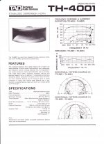
The picture below demonstrates SPL at 1.3m and radiation impedance of the biradial horn (designed by well known Japan corporation) that I simulate in ABEC3 under constant velocity condition. Radiation below the "cut-off" falls drastically.

This one?
Attachments
DI and radiation impedance do not depend on source characteristics.
In reality a driver is constant displacement below resonance, constant velocity near resonance and constant acceleration above resonance. So none of them is exactly correct. However, since we use waveguides dominantly above resonance constant acceleration is the most accurate.
What complicates things immensely is the acoustic resonance of the phase plug. This happens around the diaphragm resonance in a proper CD. At this point it is not "constant" anything, so accurate simulation have to take this into account. But the errors are not dominate in most cases (above resonance,) so just using constant acceleration is best.
Ok, let's look from another point. Power (PWT) response of a typical compression driver is approximately flat up to the mass break point (in the range of 2-3 octaves) like in the picture below.

Don't you think that if the acceleration were constant, not the velocity, the frequency dependence of the power response would look a little different ?
Last edited:
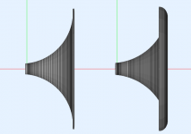
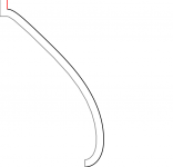
Out of curiousity, a 19" WG with a simple circular arc as the profile (1.4" throat) -
Flat edge (no rollback):

Edge rollback:

Flat edge (no rollback):
Edge rollback:
Attachments
Last edited:
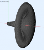
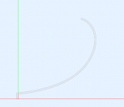
This is a shallow waveguide I presume?
It's 90° with a 1 inch throat. Here's the actual profile:
Attachments
Ok, let's look from another point. Power (PWT) response of a typical compression driver is approximately flat up to the mass break point (in the range of 2-3 octaves) like in the picture below.
Don't you think that if the acceleration were constant, not the velocity, the frequency dependence of the power response would look a little different ?
No, and here is why. A CD is a heavily damped device with a Qes down around .1 or so. This means a very broad resonance (there are actually two, but that's another dscussion,) and hence a large overlap of regions for constant displacement, velocity and acceleration. The "mass break point" is the transition from constant velocity to constant acceleration - i.e. mass controlled. Neither constant velocity nor constant acceleration is correct, velocity is more correct at LFs and acceleration at HFs.
By the way, a PWT measurement is not the power response, it is still pressure measurement, it's just that in this case the power is proportional to the pressure because of the simplified loading conditions (assuming no HOM,) which is not the case for a radiating waveguide.
Attachments
Last edited:
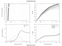
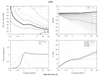
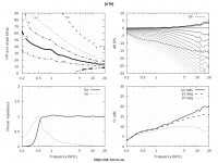
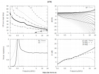
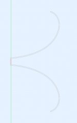
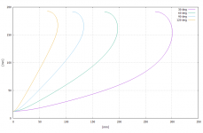
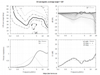
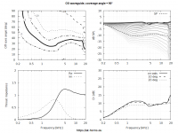
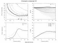
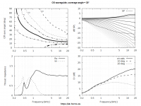
Here is a short study of four OS waveguides with different coverage angles, all having the same overall mouth diameter (about 15").
The rollback starts at 65% of the length of the profile in each case. Maybe this should be treated differently (starting at the same y value?), I don't know.
As it is, up to about 1 kHz the DIs are virtually the same, obviously given by nothing else than the mouth size.

The rollback starts at 65% of the length of the profile in each case. Maybe this should be treated differently (starting at the same y value?), I don't know.
As it is, up to about 1 kHz the DIs are virtually the same, obviously given by nothing else than the mouth size.
Attachments
- Home
- Loudspeakers
- Multi-Way
- Acoustic Horn Design – The Easy Way (Ath4)