It seems to be a matter of "building on what science has brought us over the past 120 years".
Like this:
"An acoustical transformer or "phasing plug" for coupling sound from a speaker diaphragm to the throat of a horn. The phasing plug of the invention is in the general shape of a dome on one side and a truncated cone on the other, and has evenly spaced radial slots or channels formed therein, these slots forming air passageways for propagation of the soundwaves. The walls of the slots are tapered exponentially from their inlet ends at the speaker diaphragm towards a flat plane outlet at the throat of the horn, to provide an optimum impedance match between the output of the diaphragm and the input of the horn; the sound channels formed by the slots exponentially increasing in area between their inlets and outlets. Transformation from a spherical wave front at the input to a plane wave front at the outlet is assured by the shaping of the channels to make the distances between corresponding points at the channel inlets and outlets equal to each other."
This is probably not the best example, but it has some merit nonetheless.
Last edited:
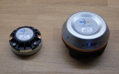
The drivers are waiting for their waveguides ")
- The smaller waveguides should arrive next week, the larger come next.
- The smaller waveguides should arrive next week, the larger come next.
Attachments
So CD itself is front loaded multi entry exponential horn (at least in this case) or some sort of band-pass with flared portsIt seems to be a matter of "building on what science has brought us over the past 120 years".
Like this:
"An acoustical transformer or "phasing plug" for coupling sound from a speaker diaphragm to the throat of a horn. The phasing plug of the invention is in the general shape of a dome on one side and a truncated cone on the other, and has evenly spaced radial slots or channels formed therein, these slots forming air passageways for propagation of the soundwaves. The walls of the slots are tapered exponentially from their inlet ends at the speaker diaphragm towards a flat plane outlet at the throat of the horn, to provide an optimum impedance match between the output of the diaphragm and the input of the horn; the sound channels formed by the slots exponentially increasing in area between their inlets and outlets. Transformation from a spherical wave front at the input to a plane wave front at the outlet is assured by the shaping of the channels to make the distances between corresponding points at the channel inlets and outlets equal to each other."
This is probably not the best example, but it has some merit nonetheless.
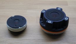
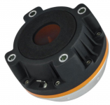
The reason I mentioned the transition is because I was looking at this picture a few days ago. It's more obvious than in the pictures Marcel posted. Just thought it was strange to have such a precision built device have such an inconsistency from the foam gasket...
Also noticed they don't give an exit angle for it...
Not trying to dump on the driver though. Am very excited to see results!
Also noticed they don't give an exit angle for it...
Not trying to dump on the driver though. Am very excited to see results!
Attachments
Last edited:
It made me wonder why is the half-rollback (180 deg only) so good termination. Here is a simple experiment with a small source placed behind the waveguide (the wavegide itself does not produce any sound). Basically I wanted to see how much sound diffracts around the device.
Here is the setup:

Here is the setup:
Attachments
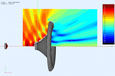
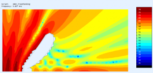
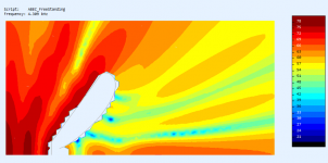
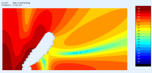
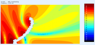
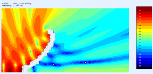
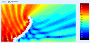

Yeah. The sound waves that diffract around the mouth edge are scattered by the rear side of the waveguide and some of this diffracts back to the listener - this causes ripple in frequency response because it is delayed. This shape seems to somwhat minimize that.
At least this seems to be the reason why a 180 deg rollback gives a smoother response than 270 deg (or more).
At least this seems to be the reason why a 180 deg rollback gives a smoother response than 270 deg (or more).
Last edited:
It can't be because of the long delay for the wave to come back from behind. In your simulation in order to simulate a real room, you would have to delay that little exciter with say at least 6 meter worth of sound travelling time. While this might be audible in "corrupting" the bounced (double!) wave in a real situation it would never effect such "hard gating" as your simulations represent. I have asked for the time aspect you know
//
//
- Home
- Loudspeakers
- Multi-Way
- Acoustic Horn Design – The Easy Way (Ath4)