nc535 has done lots of concepts around this idea, all on this thread https://www.diyaudio.com/forums/ful...ay-wall-corner-placement-143.html#post6720380
Directivity Qs.
Much care has been taken in the range covered by the WG and it seems to me the choice of approach to extend to lower frequency should be as firmly based on directivity control, especially if moving away from the most familiar option of matching directivity with that of a large bass-mid driver, which I'm not saying is a good or bad move.
Each method leads to different early reflections and power response. Decide on requirements and goals in the context of the room geometry, and perhaps Schroeder frequency, and likely speaker locations. There's also the question about how much to prioritize horizontal vs. vertical off-axis response (which may be your reason for departing from the conventional approach).
I write the rest in the specific context of using an axisymmetric or near-axisymmetric waveguide for the high frequencies.
MEH
There's one "fully engineered" solution to match mids into a horn/WG: an MEH with optimal quarter-wave matching.
It would be extremely interesting to see someone make an MEH with such a low-diffraction waveguide. Were it within my skills, or if I already had a printer set up, I'd try for certain, even if I didn't plan to build it into a speaker.
RING of MIDS around waveguide
Having played with arrays of four mids around a (basic) WG, I note that it is difficult to find satisfactory locations for the mids. The problem is diffraction, though different in detail whether the mids are behind, ported into, or immediately adjacent to the mouth of the WG.
You've already been pointed to probably the best thread on this sub-topic see #7724 - from about the middle of the thread on, there are many simulations of "rim drivers" and related options that bear close study.
CARDIOID
Cardioid may be a better fit to a WG "tweeter" than is dipole, as the horizontal directivity hand-over can be smooth, if done where the WG response is wide. It's like matching to a large bass-mid except that the directivity is more constant below the crossover, rather than widening to monopole. Also explored in nc535's thread (at tmuikku's link).
It's not obvious how to arrange (active or passive) cardioid mids in the same horizontal plane as the WG - it's easier to see how to do it in the arrangement with the mids (front and sides) below the WG, or split below and above, which may help or hinder, depending on the goals.
Even though I made fractal arrays with a ring of mids around the WG, I'd only recommend that option where there's not enough depth for an MEH or cardioid - i.e. for a special purpose, or after the more conventional options have been ruled out.
Ken
What do you think? If crossed low enough, perhaps. Maybe making it a dipole/cardioid.
(i.e. placing midrange drivers in the enclosure wall behind the waveguide)
Much care has been taken in the range covered by the WG and it seems to me the choice of approach to extend to lower frequency should be as firmly based on directivity control, especially if moving away from the most familiar option of matching directivity with that of a large bass-mid driver, which I'm not saying is a good or bad move.
Each method leads to different early reflections and power response. Decide on requirements and goals in the context of the room geometry, and perhaps Schroeder frequency, and likely speaker locations. There's also the question about how much to prioritize horizontal vs. vertical off-axis response (which may be your reason for departing from the conventional approach).
I write the rest in the specific context of using an axisymmetric or near-axisymmetric waveguide for the high frequencies.
MEH
There's one "fully engineered" solution to match mids into a horn/WG: an MEH with optimal quarter-wave matching.
It would be extremely interesting to see someone make an MEH with such a low-diffraction waveguide. Were it within my skills, or if I already had a printer set up, I'd try for certain, even if I didn't plan to build it into a speaker.
RING of MIDS around waveguide
Having played with arrays of four mids around a (basic) WG, I note that it is difficult to find satisfactory locations for the mids. The problem is diffraction, though different in detail whether the mids are behind, ported into, or immediately adjacent to the mouth of the WG.
You've already been pointed to probably the best thread on this sub-topic see #7724 - from about the middle of the thread on, there are many simulations of "rim drivers" and related options that bear close study.
CARDIOID
Cardioid may be a better fit to a WG "tweeter" than is dipole, as the horizontal directivity hand-over can be smooth, if done where the WG response is wide. It's like matching to a large bass-mid except that the directivity is more constant below the crossover, rather than widening to monopole. Also explored in nc535's thread (at tmuikku's link).
It's not obvious how to arrange (active or passive) cardioid mids in the same horizontal plane as the WG - it's easier to see how to do it in the arrangement with the mids (front and sides) below the WG, or split below and above, which may help or hinder, depending on the goals.
Even though I made fractal arrays with a ring of mids around the WG, I'd only recommend that option where there's not enough depth for an MEH or cardioid - i.e. for a special purpose, or after the more conventional options have been ruled out.
Ken
explored this topic - cardioid with small mids surrounding waveguide- in thread below using VituixWhat do you think? If crossed low enough, perhaps. Maybe making it a dipole/cardioid.
(i.e. placing midrange drivers in the enclosure wall behind the waveguide)
Full range line array for wall or corner placement
see circa post 1427
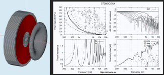
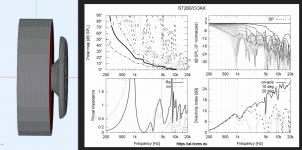
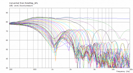
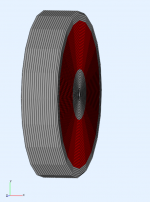
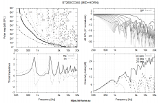
The design is based on a 300 mm diameter 1.4" exit waveguide anticipating use with HF1440. Crossover to the 4 or 8 front 5" mid woofers is at 700 Hz. There are additional 4 or 8 side woofers that provide cardioid response down to just over 100 Hz. There, the side woofer contribution is brought back in sync with the fronts to extend the low end responnse where it is excursion limited.
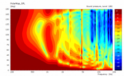
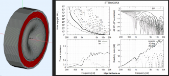
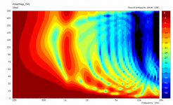
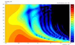
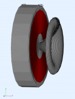
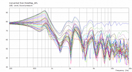
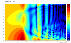
Here's just a quick simulation using an actual waveguide body considered. It's not the same as several discrete transdurers but at least axisymmetric (acoustic source is the red area) -
Seems like ~ 800 Hz would be the limit, which would fit nicely.
Seems like ~ 800 Hz would be the limit, which would fit nicely.
Attachments
Last edited:
I don't think it has any advantage. Certainly that's not how I would do it - too many small speakers spaced too far away from the CD. The acoustic integration would be unnecessarily difficult (especially in a passive crossover), IMO.
Attachments
Last edited:
the question is does it have any disadvantage? I got an abec sim of the rollback against the baffle by modifying your node.txt file to model a large disk at the edge of the rollback. This made very little difference to the sim results, although I can't now find the directory where I did that work.
I don't think the CD will "see" the small drivers surrounding the waveguide. The question is to what extent the waveguide rollback will disturb the pattern of the small drivers. that is a question I have yet to ask ABEC
I don't think the CD will "see" the small drivers surrounding the waveguide. The question is to what extent the waveguide rollback will disturb the pattern of the small drivers. that is a question I have yet to ask ABEC
That's what I showed in #7730, that's with the rollback flush to the baffle. Yes, these things are very easily done by modifying the nodes manually (nodes.txt and solving.txt), 5 minute work. That's the nice thing about axial symmetry, I wouldn't bother with full 3D. One could also as easily remove the waveguide and try it just for the midrange source, to see the influence of the waveguide as an acoustic obstacle.
My point is only that it's better/easier to have the midrange drivers in the same plane as the compression driver. (Or not?)
 Not exactly the cheapest option...
My point is only that it's better/easier to have the midrange drivers in the same plane as the compression driver. (Or not?)
You mean buying a triaxial and replacing the waveguide?Overview
The horns at least in their triaxes are removable (big thread).
Not exactly the cheapest option...
Last edited:
Why dint er like this one?
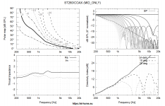
Test Bench: The BMS 1” 5530ND High-Efficiency Compression Driver | audioXpress
//
Test Bench: The BMS 1” 5530ND High-Efficiency Compression Driver | audioXpress
//
One could also as easily remove the waveguide and try it just for the midrange source, to see the influence of the waveguide as an acoustic obstacle.
My point is only that it's better/easier to have the midrange drivers in the same plane as the compression driver. (Or not?)
I would personally be very interested in the effect of the waveguide on the midrange polar response - not an easy thing to do without numerical computations.
I have found that the CD should be well behind the midrange, thus putting the two in synch after the LP filters delay.
- Home
- Loudspeakers
- Multi-Way
- Acoustic Horn Design – The Easy Way (Ath4)