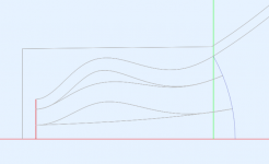
Back to the throat plug resonance mystery - I think it may be the extra volume of air within the channels that's actually added. By prolongating the outer channles, there is an extra volume/mass/compliance that's not there otherwise. The throat and the exit of the "plug" both stay the same but the interior is "inflated"...
So in fact, the total cross section area increases and then shrinks again. Hence the resonance (which may be a good thing after all, as it increases the efficiency where we need it the most).
The bends themselves appear acoustically as compliance, as I understand it. The path length through a bend is shorter than the ‘simple path’ would suggest, and the total horn length is typically extended to compensate. That’s how it works with the ‘advanced centreline method’ for bass horns, anyway.
I’m not sure if you’ve already considered this when specifying the equation for generating your path-length correcting bends or not?
Also, is there any observed difference if you approximate the curved diaphragm shape of the radiating surfaces rather than using a flat plane? So the normals match the angle of the centre line at the initial part of the channel, for example.
I think I have nailed it - the bended/protuberant channels effectively form kind of a chamber with a narrowed exit.
Otherwise, the exit wavefront should be formed quite coherent as the simulated HF polars show - it wouldn't be so nice if it didn't. So the relative timing is correct, I think. There's virtually no difference with spherical sources compared to the flat segments.
Otherwise, the exit wavefront should be formed quite coherent as the simulated HF polars show - it wouldn't be so nice if it didn't. So the relative timing is correct, I think. There's virtually no difference with spherical sources compared to the flat segments.
Attachments
Last edited:
I can't help with the flat panels (still on the TO-DO list) but I think you could still print it as the "base+petals" construction, which is not that resource intensive. Any shape can be divided into these parts easily, especially if you are handy with CAD.
Do you have a measurement for this and is it CD?
Thanks!
The kind people at Celestion provided this information for the lumped model
Sd = 78.82cm2
Bl = 11.52Tm
Cms = 7.51e-5
Rms = 0.5
Mmd = 1.17g
Le = 0.05mH
Re = 5.6 ohms
Vtc = 38.0cm3
Atc = 78.82cm2
If Atc is the same as Sd then the compression ratio will be 1.0. I am guessing that Atc is the area at the end of the phase plug - the other side of the volume Vtc, i.e. the diaphragm. Otherwise there is no specification for the compression ratio, which is essential for an accurate model.
I would think Vtr (assuming that is the resistance) would be minimal. Atr could be significant, but when we looked at this at B&C, we found that it really wasn't.
Last edited:
The bends themselves appear acoustically as compliance, as I understand it.
A "channel" is dominantly mass, unless there is a restriction in one area that thus encloses a volume, just as Marcel is suggesting.
David (and Earl),To complete the model, values also have to be specified for Vrc and Lrc.
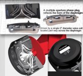
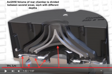
Unlike a standard compression driver, the Celestion AXi2050 annular "ring radiator" corrugated diaphragm Vrc (Volume rear chamber) is divided into three (or four) chambers each of different length (Length rear chamber) with restrictions connecting them.
It's phase plug also has three entrance points coinciding with distinct portions of the diaphragm- outer, voice coil ring, and inner.
Lumping the rear chamber's volume and length may be too simplistic for this particular driver.
Art
Attachments
Last edited:
Lrc in Hornresp is "Length rear chamber".
As can be seen in the attachments in #8566, each Vrc portion of the Celestion AXi2050 also has a different Lrc.
Also, it's Sd = 78.82cm2 is about the same as a 4" dome shape diaphragm, but the annular ring is pinned at each side- no movement at all on the inner and outer portion, about 1mm excursion center, if I recall correctly, roughly equivalent to a typical 4" compression driver with a .5mm Xmax.
It took a long time for Celestion to get it to work...
Last edited:
David (and Earl),
Unlike a standard compression driver, the Celestion AXi2050 annular "ring radiator" corrugated diaphragm Vrc (Volume rear chamber) is divided into three (or four) chambers each of different length (Length rear chamber) with restrictions connecting them.
It's phase plug also has three entrance points coinciding with distinct portions of the diaphragm- outer, voice coil ring, and inner.
Lumping the rear chamber's volume and length may be too simplistic for this particular driver.
Art
Hi Art,
Thanks for this information. Any lumped-element model of the Celestion Axi2050 compression driver is going to be an approximation at best
") .
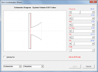
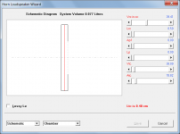
.Attachment 1 shows the driver as originally specified in the post by 'aragorus', with no sealed rear chamber.
Attachment 2 shows the driver with a rear chamber added. The rear chamber size is a guess on my part.
Attachment 3 shows the model with the phasing channels separated out as a separate element. Once again just a guess on my part, but the overall volume of the now smaller front chamber plus the phasing channels has been kept the same as the Vtc volume given by Celestion. I would be inclined to use this slightly more refined model if I wished to use the driver in a simulation.
In all three cases the driver outlet diameter is 50 mm (cross-sectional area = 19.63 cm^2).
Kind regards,
David
Attachments
Why would the miniscule length of the rear chamber in a compression driver be a factor? Volume, yes, length, no.
In this case length is not really a factor.
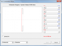
Hornresp models a chamber as a cylindrical tube. With a rear chamber, the tube is closed at one end. Although volume is specified as one of the input parameters, the actual calculations use cross-sectional area and axial length when determining volume velocities, pressures and acoustical impedances.
Hornresp does not normally treat a chamber as a simple compliance, where just volume is required. It only does so if the "resonances masked" option is selected.
Another reason why axial length is an input parameter in Hornresp is so that the chamber can be accurately represented in the axisymmetric schematic diagram.
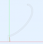
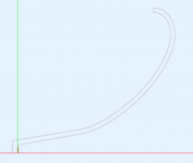
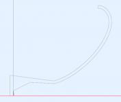
It may not be so obvious from the picture - these are the channel areas (normal to the wave propagation) calculated for the example below.- the bended/protuberant channels effectively form kind of a chamber with a narrowed exit.
Attachments
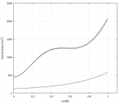
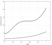
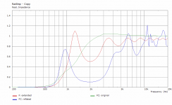
Ah yes, since the channels get further from the rotation axis the volume increases. It is sometimes hard to think a 2D presentation in 3D and vice versa It is cool you found the reason for impedance shape so quick and confirmed it with an experiment.
If one would like to get rid of the volume increase the channels shouldn't bulge at all? That leaves the lengthening be rotation like with the Berstis lens, but that had some other problems.
Is this problem at all if the response is nice?
edit. if you bulge the center channel, doesn't that allow the channels to be removed completely? Just have the throat bulge as with the experiment without any channels at all? Is the polars of the highs better with the channels? If it is I think the takeaway here is that the bulging throat gives the loading and the channels can improve the polar response at the top octave. Can you optimize bot separately? Maybe a bulging throat for loading with just one channel at middle for the top octave?
It is cool you found the reason for impedance shape so quick and confirmed it with an experiment.If one would like to get rid of the volume increase the channels shouldn't bulge at all? That leaves the lengthening be rotation like with the Berstis lens, but that had some other problems.
Is this problem at all if the response is nice?
edit. if you bulge the center channel, doesn't that allow the channels to be removed completely? Just have the throat bulge as with the experiment without any channels at all? Is the polars of the highs better with the channels? If it is I think the takeaway here is that the bulging throat gives the loading and the channels can improve the polar response at the top octave. Can you optimize bot separately? Maybe a bulging throat for loading with just one channel at middle for the top octave?
Last edited:
Actually I already quite like it as it is - it increases efficiency on the lower end of the passband (allowing to cross a driver lower) without negatively affecting high frequencies (at least not too much, it seems). What's not to like?
It already occured to me, I will surely try that as well.edit. if you bulge the center channel, doesn't that allow the channels to be removed completely?
Last edited:
Yup, you should print one and check out how it measures and sounds I think.
Hmm looking at it as simplified bulging throat without the channels, is it diffraction device then after all, loading by longer throat section and then a diffraction slot to make the wider polars at the top? As you try to stretch the bandwidth either way the other end follows. The channel version can very well be the ultimate stretch out between loading and pattern control.
I'm not sure if this is something that is useful for home hifi. For PA work perhaps, better loading and pattern and possibly better sound quality over diffraction slots. Never know until tested. I think there could be application for MEH duty Conical section would allow mounting MEH mids and while they are a bit further out of the compression driver due to the tulip part, the extra loading would help bring the xo lower in frequency. This could possibly allow ATH optimized ~90 deg nominal MEH nicely?
Hmm looking at it as simplified bulging throat without the channels, is it diffraction device then after all, loading by longer throat section and then a diffraction slot to make the wider polars at the top?
As you try to stretch the bandwidth either way the other end follows. The channel version can very well be the ultimate stretch out between loading and pattern control.I'm not sure if this is something that is useful for home hifi. For PA work perhaps, better loading and pattern and possibly better sound quality over diffraction slots. Never know until tested. I think there could be application for MEH duty
Conical section would allow mounting MEH mids and while they are a bit further out of the compression driver due to the tulip part, the extra loading would help bring the xo lower in frequency. This could possibly allow ATH optimized ~90 deg nominal MEH nicely?
Last edited:
It would be a very smooth diffraction device. But I'm not sure that it will be possible to remove the channels without too much diffraction stepping in. The more bending, the more narrow the channel must be to behave "simply".
If it works as simulated, I think it will be quite useful especially for home hifiI'm not sure if this is something that is useful for home hifi.
Last edited:
The other way around, not bulging the center channel, one could try and make the area expansion of all the channels the same while still doing the length adjustment. It will look like a pinched channel while it isn't in expansion. What that does to the impedance I'm not even going to predict . Worth a try?
. Worth a try?Hmm pinching.. ain't the increased volume and then a pinch work as acoustic low pass? In which case it makes the high frequency source apparently smaller concentrated at the center (channel), which helps the polars up top? In which case there could be possibility to improve overall performance by the bulge / pinch relation, maybe apply some rollback to the center channel? Pinch on the center channel would allow balance the high frequency content to that on the outer channel. Just a thought. Following eagerly where this evolves
Last edited:
I'm not sure I follow, you'd have to draw me a sketch.The other way around, not bulging the center channel, one could try and make the area expansion of all the channels the same while still doing the length adjustment. It will look like a pinched channel while it isn't in expansion. What that does to the impedance I'm not even going to predict
- The main motivation is still to present a clean spherical wavefront to the waveguide (so that bigger drivers can be used without beaming). The rest is just a by-product at the moment.
- Home
- Loudspeakers
- Multi-Way
- Acoustic Horn Design – The Easy Way (Ath4)