Well, obviously the area expansion is because of the larger diameter at that spot. So if you pinch the channel there in 2D the 3D area can remain constantly growing just like the center channel.

Shouldn't be too hard to figure out how to keep the length while making the area expansion behave like the center channel or at least have it expanding regularly.
Edit: the end of the channels should be pinched too while the center channel should expand more to get it close to equal area expansion in every channel.
Attachments
Last edited:
So the larger the radial offset, the thinner the channel by a factor (insert part of a circle area equation here)
That could maybe be done by multiplying all the X coordinates by a factor of x. It will ofcorse change the radius of the whole thing, but it could be adjsted afterwards..
That could maybe be done by multiplying all the X coordinates by a factor of x. It will ofcorse change the radius of the whole thing, but it could be adjsted afterwards..
Last edited:
It might just work with the 3 turns, and calculated according to the area. It will look rather different than expected in 2D due to the changes in radial offset. But it would be quite interesting to see what results that would give. Making it based on equal area's.
Wasn't there a phase plug design by Dr. Geddes that had an equal area division?
Dr. Geddes' Phase Plug Design
Wasn't there a phase plug design by Dr. Geddes that had an equal area division?
weltersys said:The Summary Of The Invention (0013) states:
"In the Fresnel zone concept, each zone is of equal area. The number of zones is arbitrary except that there should be the same number at the diaphragm and the exit aperture and there are the same number of concentric annulus channels as Fresnel zones"
(0014) states:
"Usually, the phase plugs exit aperture is identical to the waveguides throat, or entrance.."
Dr. Geddes' Phase Plug Design
FWIW, I tried the above (i.e. all channels had the same area as a function of length) and it didn't make a principal difference. So obviously it's only the total what matters.I'm not sure about the importance but it probably would be easy to adjust the channels to have the same area expansion. The center channel would need to bend as well.
Only now I finally understand how did you mean that. That should be possible, I'll definitely try that.Well, obviously the area expansion is because of the larger diameter at that spot. So if you pinch the channel there in 2D the 3D area can remain constantly growing just like the center channel.

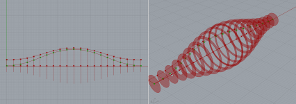
I've started from scratch...
1 single meander by the means of 2 bezier curves
then offsetting the curves by a factor, so that the area of the "disks" is the same.
For now I'm trying to make a straight "tube" with no expansion towards the mouth.
So if I want to offset the channel with X mm, every point gets offset by X - sqrt(X)
This gets me close, but I'm sure there is a better function that will get all the areas to be the same.
...when I get it close enough I'm curious to see how it will compare with the results for a straight tube
Attachments
Last edited:
I'm really curious about the outcome.
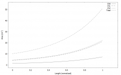
- I use an iterative calculation method to get the channel lengths equal. Not very pretty but effective. I doubt there is a simple analytic approach but maybe there is. To vary the widths of the channels to get a monotonically (exponentially?) increasing total area should not be very difficult. Seems like a straightforward extension to what I already have - first I construct the center lines of all channels and then set the widths according to some rule, which can be anything.
- I use an iterative calculation method to get the channel lengths equal. Not very pretty but effective. I doubt there is a simple analytic approach but maybe there is. To vary the widths of the channels to get a monotonically (exponentially?) increasing total area should not be very difficult. Seems like a straightforward extension to what I already have - first I construct the center lines of all channels and then set the widths according to some rule, which can be anything.
Last edited:
Yes, that is a good approach!
I'm trying to do it in a parallel way with grasshopper even though it's a bit more time consuming to get the logic together. It's pretty intuitive after that.
The way I would like to tackle it is to start from the center and offset outwards for every channel. Not 100% sure it will work getting the equal lengths in the end but it's a good exercise
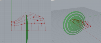
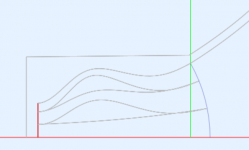
In this scenario, I've divided the throat (plannar) and the exit (spherical) in to equal area rings.
The meanders consist of 2 bezier curves start to mid and mid to end.
This however doesn't give quite the precision that is required to match the area at every "slice"
I also noticed that the subdivision slices for comparing the area (green) are not always normal to velocity, so I have to rethink how I subdivide the curves..
I believe the best way to do it is to work point by point where every "column" of points follows a certain formula, that keeps both the area and meander length in check. Not sure yet how to implement that, but I'm sure it's possible.
It's quite an interesting problem to solve
Attachments
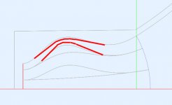
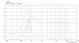
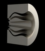
OK, here's the try - the outer channels "pinched" so that the area is only increasing. Seems to change something
(1.4" driver)
What it probably still needs is an adjustment of area expansion to better match the plug and the waveguide entrance.
This is a good stuff, guys.
(1.4" driver)
What it probably still needs is an adjustment of area expansion to better match the plug and the waveguide entrance.
This is a good stuff, guys.
Attachments

Last edited:
Yeah, exponential for best loading or conical to match the driver exit section or anything between, what ever is teh holy grailiest
Could the waveform curvature be changed arbitrary as well? I mean if the driver has almost spherical wave already, but not quite, the tulip could correct the rest? Assuming the driver exit waveform was known. Just a thought
Could the waveform curvature be changed arbitrary as well? I mean if the driver has almost spherical wave already, but not quite, the tulip could correct the rest? Assuming the driver exit waveform was known. Just a thought
Last edited:
So who is able to make it?
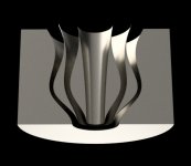
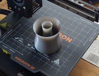
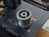
- I already tried a half on a regular FDM printer (0.25 mm nozzle) and at least for prototyping it's pretty good. The top is a single perimeter, so about 0.25 mm thick (would need some hardening though, maybe an epoxy coat, or just make the wall thicker). There are still also some minor slicer issues.
- I already tried a half on a regular FDM printer (0.25 mm nozzle) and at least for prototyping it's pretty good. The top is a single perimeter, so about 0.25 mm thick (would need some hardening though, maybe an epoxy coat, or just make the wall thicker). There are still also some minor slicer issues.
Attachments
- Home
- Loudspeakers
- Multi-Way
- Acoustic Horn Design – The Easy Way (Ath4)