Maybe @CinnamonRolls, you would like check with an insert if it is possible to reduce the opening of the CD beyond the smaller diameter width of the conical section?
What I mean I wrote about when the discussion was still all about throat inserts for uninterrupted curve: https://www.diyaudio.com/community/...-design-the-easy-way-ath4.338806/post-7350058 It seems a flat sided section is okay, however.
It might be that it comes without punishment to simply reduce the aperture of the CD. This would allow much better high end dispersion for any driver that can take an ring insert.
In practice, I have been reducing the DE250 exit from 19mm to 18mm in all the Internal Rings I printed for the REW measurements. I've also reduced further than 18mm by including the fins and other features inside the Internal Ring (restricting total aperture size) but I didn't realize it until thinking about it just this moment. If I added too many structures inside the Internal Ring duct it would reduce output similar to stuffing Rockwool inside the duct.
I've also accidentally included abrupt changes in the duct such as when I accidentally left a gap between the internal ring and the waveguide. Despite that mistake, the directivity still matched the simulations. The duct impact on directivity is very resilient compared to the termination and rear features of the waveguide - e.g. the large size DE250 on the back of a smaller sized waveguide.
This is what being clueless and careless looks like. All these because I wasn't careful to check for a gap between the Internal Ring and the waveguide on the first try. However, none of them destroyed the off-axis measurements. BTW, that's Aquarium sponge in the background, 30 PPI. I tried that in the duct too. It didn't seem to have positive effects in terms of impedance so I abandoned it. Although, it looked good and would make a good bug/dust screen for the compression driver exit.
Last edited:
Actually, for a DIY there are not many excuses why not to do it anymore
Yep, now I can open up my DE250 and clean out all the junk I accidentally dropped in there while changing out internal rings. I look forward to seeing your large diameter Radian compression drivers in action. They'll be a world first that will blow everyone's minds with their performance.
In practice, I have been reducing the DE250 exit from 19mm to 18mm in all the Internal Rings I printed for the REW measurements. I've also reduced further than 18mm by including the fins and other features inside the Internal Ring (restricting total aperture size) ...
While the fins reduce the surface area, they do not reduce the width of the source, and hence leave diffraction induced high frequency beaming. What happens if a 15 mm diameter ring is inserted? If it is not detrimental, choosing the aperture width of the compression driver could be dealt with independent of what is achievable based on exit angle given by a certain model and allowed free control over source size.
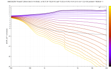
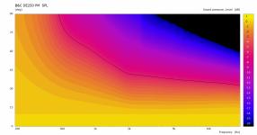
The B&C DE250 has a 19mm exit from the phase plug followed by a 25mm long conical duct with a final 25mm diameter exit. The internal rings I printed and measured in REW for the B&C DE250 all had 18mm inner diameters. Then I printed sleeves to place inside an empty 18mm duct to try different fin shapes. Those were 18mm outside diameter and apprx 17mm inside diameter. I was able to insert and remove them from the empty 18mm Internal Ring duct. You can see the sleeves in the previous photograph in post #12,992.
Here's a simulation for a DE250 that reduces from a 19mm phase plug exit to a 15mm diameter internal ring. It is sized so that you could 3D print an Internal Ring that would comfortably fit inside the DE250's conical exit and still be 1mm thick at the thinnest portion of the Internal Ring. I attached a zipped folder with the waveguide files if you want to make modifications and run simulations. (ABEC.MeshFrequency = 80000)
Nodes:
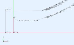
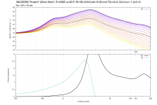
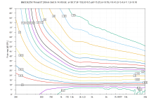
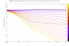
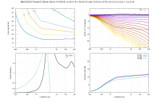
217 3.000 7.500
218 7.000 7.500
219 12.500 7.500
220 12.500 7.500
221 12.500 7.500


Attachments
Last edited:
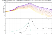
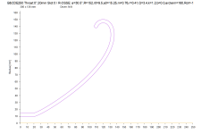
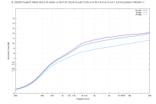
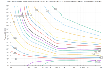
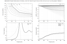
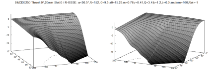
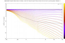
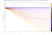
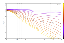
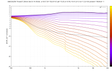
Arcterm did not prevent my printed waveguide from generating impedance reports. I still don't know what the problem is on that config file but here's a narrower waveguide with arcterm and the impedance report works fine. These reports created with ATH 4.9.0-230531 at ABEC.MeshFrequency = 80000. Internal Ring reduces from 19mm to 17.5mm, which was an arbitrary choice because I was trying to see if the raw SPL/impedance report would work.
I don't know if my thinking is correct on this waveguide but I slightly increased the higher frequencies for the speaker that is furthest from the listener in a home theater side by side sitting arrangement. I'm trying to compensate for higher frequencies falling off over distance. Boost the further speaker a little to make it match the closer speaker. However, it's only higher by 1/4 dB so maybe that isn't enough to notice. Zip contains configuration files.
Nodes:
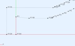
217 7.000 8.750
218 7.000 8.750
219 17.000 8.750
220 17.000 8.750
221 17.000 8.750


Attachments
Last edited:
Wouldn’t it be nice then to actually know?I would still be hesitant about reducing the throat area substantially under that of a phase plug exit.
Interesting. This rule would leave us with about 17.5 mm, which comes as only the slightes reduction at the chamber for a DE250, from 19 mm. What is this rule derived from and which factors are relevant, in your opinion?Typically it's possible to go one size lower (1.4" -> 1", etc.).
I will check the results for the high frequency dispersion for 17.5 mm for a wide waveguide the next time I have access to a working ath, my laptop installation is currently not creating ABEC projects.
Last edited:
It's just an observation. The only relevant factor is really the construction of the driver, IMO, as some are more suitable than others, perhaps.What is this rule derived from and which factors are relevant, in your opinion?
- To know means to actually try it. Just go for it
(The sims already tell a lot but typically we don't simulate complete drivers, which still leaves some room for unexpected results.)
Yes, Marcel, I know.To know means to actually try it. Just go for it
Still do not have the printer, why I asked if someone wanted to check the effect who already can. But at some point, I can do it.
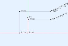
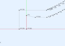
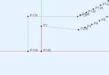
Wanted to see how shifting the initial reducing node from near the phase plug out to start of the waveguide changed impedance.
DE250 reduced from 19mm to 16.4mm (I accidentally set r0=8.2 rather than 8.0) then moved the reducing node (P200) from very close to the phase plug all the way out to the start of the waveguide (P2). MeshFrequency=30000.
P200 set at 0.5mm from phase plug
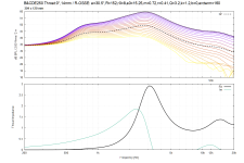
P200 = 1mm
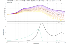
P200 = 2mm

P200 = 4mm
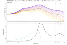
P200 = 6mm
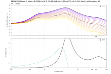
P200 = 8mm
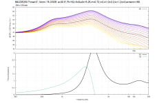
P200 = 10mm
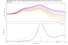
P200 = 12mm
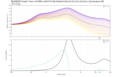
P200 = 14mm (start of waveguide)
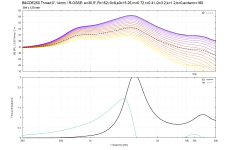
DE250 reduced from 19mm to 16.4mm (I accidentally set r0=8.2 rather than 8.0) then moved the reducing node (P200) from very close to the phase plug all the way out to the start of the waveguide (P2). MeshFrequency=30000.


P200 set at 0.5mm from phase plug

P200 = 1mm

P200 = 2mm

P200 = 4mm

P200 = 6mm

P200 = 8mm

P200 = 10mm

P200 = 12mm

P200 = 14mm (start of waveguide)

Attachments
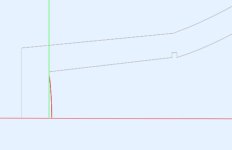
B&C DE250 simulation of factory conical throat exit. Three variants: 1) waveguide starting directly from end of plastic conical throat, 2) waveguide on steel surface - gasket and bug screen removed, and 3) waveguide on gasket. The plastic conical throat is recessed 1mm below the steel surface of the compression driver creating a 1mm wide step I called a "Lip" because that's how I viewed it from the perspective of creating Internal Rings to insert inside the throat.
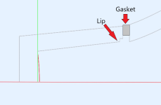
The phase plug and conical section is plastic. The "Lip" of the plastic conical section is recessed 1mm below the steel surface. The gasket is 2mm thick.
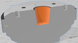
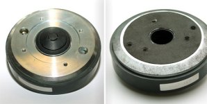
Conical Throat: (My measurements tools aren't precise, don't rely on the following measurements.)
Throat Exit Diameter 25.4mm
Throat Length 25mm
Phase Plug Exit Diameter 19mm
Exit Half-Angle 6.843° (calculated from my measurements)
Factory spec sheet impedance B&C DE250. (Link to B&C Speakers DE250 website page)
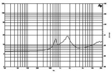
Simulated waveguides are not matched to conical throat exit angle. I set a0 = 1/2 a to match the horn coverage angle. I don't know but I assume manufactured horns don't try to match compression driver exit angles. And in practice they probably don't when DIYers purchase horns and compression drivers in the aftermarket. I included the config file, nodes.txt, and solving.txt in the Zip if you want to match a0 to the factory conical exit angle.
1) Waveguide starting directly from conical throat exit, no Lip
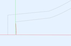
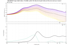
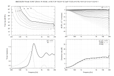
2) Waveguide set on steel surface (gasket and bug screen removed from compression driver).
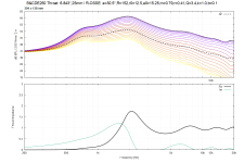
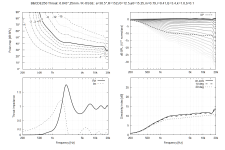
3) Waveguide set on top of gasket and bug screen.
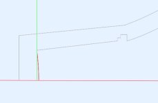
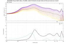
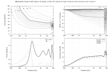

The phase plug and conical section is plastic. The "Lip" of the plastic conical section is recessed 1mm below the steel surface. The gasket is 2mm thick.


Conical Throat: (My measurements tools aren't precise, don't rely on the following measurements.)
Throat Exit Diameter 25.4mm
Throat Length 25mm
Phase Plug Exit Diameter 19mm
Exit Half-Angle 6.843° (calculated from my measurements)
Factory spec sheet impedance B&C DE250. (Link to B&C Speakers DE250 website page)

Simulated waveguides are not matched to conical throat exit angle. I set a0 = 1/2 a to match the horn coverage angle. I don't know but I assume manufactured horns don't try to match compression driver exit angles. And in practice they probably don't when DIYers purchase horns and compression drivers in the aftermarket. I included the config file, nodes.txt, and solving.txt in the Zip if you want to match a0 to the factory conical exit angle.
1) Waveguide starting directly from conical throat exit, no Lip


2) Waveguide set on steel surface (gasket and bug screen removed from compression driver).


3) Waveguide set on top of gasket and bug screen.


Attachments
...and the big one for the 760NeoPB:I managed to setup a sim of a hexagonal horn, including the throat adapter.
I'm actually quite happy with this. Also tried some higher order polygons but it just loses the charm.
Perhaps it is not as pristine as a round one after all (difficult to say at the moment) but what came out as a surprise is the directivity, which seems even better controlled than of a corresponding round horn. Maybe this segmented shape could be further shifted towards a bit more rising-DI, i.e. made a bit deeper and maybe also even a bit smoother.
It will need a name. Thinking about R-OSSE Diamond.
Last edited:
Like this, but these are already nuances...Maybe this segmented shape could be further shifted towards a bit more rising-DI
(This is 33mm throat.)
I need no more
For maybe the two last years, every time I came up with something I considered good indeed, the next month I came up with something even better. Now it's really time to stop and finally build it, I want to believe...
Last edited:
BTW, six petal sheets laser-cut from 0.5mm brass (as a top layer) would be ~ €75. Considerably more than aluminum but still not bad and I think it would look awesome.
Casting clear epoxy is the ultimate goal however. It can be done per sheet/petal, which is a great advantage here.
Casting clear epoxy is the ultimate goal however. It can be done per sheet/petal, which is a great advantage here.
Last edited:
- Home
- Loudspeakers
- Multi-Way
- Acoustic Horn Design – The Easy Way (Ath4)