Impedance reports for the 46 degree DE250 waveguide I tested with the 3D printed Internal Rings. This just moves a single point around. I'll make a second post with an Internal Ring I think would be best - as long as it doesn't create problems like distortion or something.
P200 = 22.500 9.000 (The original empty 18mm diameter straight duct)


P200 = 9.000 5.000


P200 = 15.000 6.000


P200 = 17.000 6.500


P200 = 17.500 7.000


P200 = 18.000 7.250


P200 = 19.000 7.750


P200 = 22.500 9.000 (The original empty 18mm diameter straight duct)
P200 = 9.000 5.000
P200 = 15.000 6.000
P200 = 17.000 6.500
P200 = 17.500 7.000
P200 = 18.000 7.250
P200 = 19.000 7.750


A hexagonal version with a 1" throat (e.g. Faital HF146 with an inserted ring):


(Note that the impedance is calculated for the 1" throat area.)
The mouth dimensions are 600 x 520 mm (the longer x shorter "diameter").
(Note that the impedance is calculated for the 1" throat area.)
The mouth dimensions are 600 x 520 mm (the longer x shorter "diameter").
Simulated the empty duct with the 2.77mm Gap to match against measurements from post 12,890.
Includes DE250 conical throat at start where Internal Ring started and the Gap in front of waveguide as well as an apprx 2mm long flat duct in front of waveguide. The 3D printed internal ring wasn't a perfect fit so this is as close as I can get with the simulation.
Nodes:


Includes DE250 conical throat at start where Internal Ring started and the Gap in front of waveguide as well as an apprx 2mm long flat duct in front of waveguide. The 3D printed internal ring wasn't a perfect fit so this is as close as I can get with the simulation.
Nodes:
1 0.000 9.500
199 1.000 9.6281
200 1.000 9.000
201 17.730 9.000
202 17.730 11.76945
203 20.500 12.124
204 20.500 9.000
I don't know what Lumped Element modeling is but I'm wondering if it would improve the simulation for the DE250. B&C doesn't list these specs on their website so I'm going to ask their tech support if they can supply the information.
Here's the Generic25.txt from ATH/lib/drivers
BC DE250 Specs from https://www.bcspeakers.com/en/products/hf-driver/1-0/8/de250
Here's the Generic25.txt from ATH/lib/drivers
Def_Driver 'Drv1'
dD=44mm
Mms=0.8g
Cms=30e-6m/N
Rms=3.0Ns/m
Bl=7.5Tm
Re=6.3ohm
fre=35kHz ExpoRe=1
Le=0.1mH ExpoLe=0.618
System 'S1'
Driver 'D1' Def='Drv1' Node=1=0=10=20
// Rear volume
Enclosure 'Eb' Node=20
Vb=50cm3 Qb/fo=0.1
// Front volume
Duct 'D1' Node=10=200
dD=44mm Len=0.5mm
// Phase plug (simplification)
Waveguide 'W1' Node=200=300
STh=1.52cm2 dMo=20mm Len=22mm Conical
// Conical section between phase plug and exit
Waveguide 'W2' Node=300=400
dTh=20mm dMo=25.4mm Len=22mm Conical
RadImp 'Throat' Node=400 DrvGroup=1001
BC DE250 Specs from https://www.bcspeakers.com/en/products/hf-driver/1-0/8/de250
Nominal Impedance 8
Minimum Impedance 7.8
Voice Coil Diameter 44 mm (1.7 in)
Winding Material
Inductance 0.11 mH
Material Flux Density 1.85 T
To add an LE model means to include also the driver's internals (electro-mechano-acoustical), modeled as a network of "lumped elements", i.e. discrete parts of an equivalent circuit, e.g. like this: https://pub.dega-akustik.de/ICA2019/data/articles/000394.pdf
It would bring you closer to the real absolute SPL values for a given input voltage as a function of frequency and show the diaphragm excursion, among other things. Without it, the source is modeled only as a vibrating surface at the throat (typically with a constant acceleration or velocity). It works surprisingly good, though, regarding the acoustic horn features.
It would bring you closer to the real absolute SPL values for a given input voltage as a function of frequency and show the diaphragm excursion, among other things. Without it, the source is modeled only as a vibrating surface at the throat (typically with a constant acceleration or velocity). It works surprisingly good, though, regarding the acoustic horn features.
Last edited:
- I've found a bug in the segmented horn calculations. There was a slight angle mismatch at the adapter/petal interface as a result. The funny thing is that it helped to widen the radiation pattern at HFs (that's why I noticed that a segmented horn seemed actually better-controlled than a round one). Now I wonder if I should keep it there or not ")


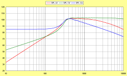
This is the ST260-SEG after fixing the bug (basically indistinguishable from the round one):


This is the ST260-SEG after fixing the bug (basically indistinguishable from the round one):
Last edited:
It might do depending on how far different it is from the generic profile. You can curve fit the impedance using the Expo Re and Le parameters so that you get a better match between real and simulation.I should have said, I wonder if adding a LE model specifically for the DE250 will improve the simulation. Too late to edit my previous post.
Conical Throat: (My measurements tools aren't precise, don't rely on the following measurements.)
Exit Half-Angle 6.843° (calculated from my measurements)
As reported in another thread ( sorry, I haven't cited the link ) the DE250 exit angle is 14.6 degrees, so half would be 7.3 degrees, perhaps that will be of value to you.
No I don't think that adding a diffraction like that is a good thing.Or add a new feature "generate a slight angle mismatch at t = {...} positions of R-OSSE curve". Maybe it could widen radiation pattern even more.
Actually, the mismatch caused lower 'k' values for the adapter, and it's enough to set it lower deliberately - easy:
Yes, I think that's more accurate. Thank you.As reported in another thread ( sorry, I haven't cited the link ) the DE250 exit angle is 14.6 degrees, so half would be 7.3 degrees, perhaps that will be of value to you.
I wonder if adding a LE model specifically for the DE250 will improve the simulation.
In my experience simulation results can vary considerably depending on whether a lumped-element driver, constant diaphragm velocity or constant diaphragm acceleration model is used as the source. Unsurprisingly, in most cases the constant diaphragm velocity model will produce the "best" overall result. Unfortunately the actual measured performance of the system, using a real driver, is unlikely to match that idealised result.
Attachments
ST260HEX
For those capable to work on it further, here's the hexagonal ST260. It's a script for Fusion 360 that imports the adapter and the petal contours as sketches. All is then done by the loft command, etc.
The throat adapter must be 3D-printed but the petals I can imagine even of a reinforced paper, or just anything else...
Have fun!
https://at-horns.eu/ext/ST260HEX.zip
Last edited:
- Home
- Loudspeakers
- Multi-Way
- Acoustic Horn Design – The Easy Way (Ath4)