TNT, Kimmosto demonstrated earlier this year that smoother power response can be achieved with cc ~1.4 wl, and worst case is about .5-.7 if i remember, this removes need to push the waveguide over the woofer unless you can drop down the xo enough to achieve near 1/4 wl c-c with the ath waveguide. Less diffraction problems at least.
Link?
")
Off topic unless ...
As the topic is currently remote from MEH, I'll reply once, briefly.
Nice - would be good to follow this. Do you have a thread somewhere? It will be interesting to see how the slots work.
Yes, experiments are best.
My intuition leads to big, less affordable, still two-way, perhaps with cardioid bass below. More closely inspired by mark100's recent projects (but with printed throat and MEH ports, at least). But I have no idea how to set about making something like that, have no printer, almost zero experience with 3D CAD etc., and have limited woodworking skills, so for now I'm watching and musing.
Ken
As the topic is currently remote from MEH, I'll reply once, briefly.
Working on it.
Nice - would be good to follow this. Do you have a thread somewhere? It will be interesting to see how the slots work.
Yes, experiments are best.
My intuition leads to big, less affordable, still two-way, perhaps with cardioid bass below. More closely inspired by mark100's recent projects (but with printed throat and MEH ports, at least). But I have no idea how to set about making something like that, have no printer, almost zero experience with 3D CAD etc., and have limited woodworking skills, so for now I'm watching and musing.
Ken
In High Quality Horn Loudspeaker Systems: History, Theory and Design Bjørn mentioned an unexplored possibility to get a gradual transition in the boundary condition at the mouth by a series of holes/openings. The technique is used in some high speed train tunnels to mitigate the sonic boom problem.
In my mind this might a viable option to try when there is no need to print the entire horn but rather exchange petals on the throat part.
If anybody wants to try to overlap the horn over a midrange driver, then the work done by PK-sound is rather interesting to have in the back of the scull. COHERENT MIDRANGE INTEGRATOR (CMI)
Link?
For example:
https://www.diyaudio.com/forums/multi-way/371070-talk-xo-10k-hz-1-4-wl-law-2.html#post6621599
It's a theme of kimmosto's stated concisely in that post.
I've been thinking about this point in the context of getting early reflections and power response in order. It helped enormously with my latest speakers.
Ken
^ and in many other occasions, try search his post history. This is quite easy to test in vituixCAD, use diffraction tool to produce measurements, add crossover (simple dsp hi and low pass components) and tune the Y coordinate of either driver assuming the measurements were done in the diffraction tool mic on axis of each driver. Yeah, not accurately what happens in reality but the effect of c-c can be inspected. With a freestanding waveguide one can plan for adjustable heigh and measure which c-c yields best results.
Last edited:
mabat, have you concidered a snap on design for the petals? I did something like that for a horn I printed a while ago.
Login • Instagram
And it's pretty easy to weld the parts using a soldering iron at 170-180 degrees
Login • Instagram
And it's pretty easy to weld the parts using a soldering iron at 170-180 degrees
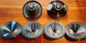
Just for fun and inspired also from this thread, I started to build some multicell horns using 3D printed shells.

What would be the recommended material to fill the gaps? Compared to the petals, this would be quite large volume, but one side opened. Would e.g. low expanding polyurethane foam work? That would be relatively easy to cut off once hardened with a sharp knife, since the printed parts will be in the end visible only from inside (most probably painted there somehow). But I am afraid it would smash the thin walls printed in vase mode.
I get a lot of mixed advice from internet and would like to know you experience. I was e.g. told polyester resins heat up more than epoxy (depends on exact type I guess).
I agree competely. It requires some filler and sanding but there's nothing like it when it comes to the ease of work. IMO the biggest advantage is that it holds almost instantly. I had to fix some places and this was about the only way of doing it with only two hands.And it's pretty easy to weld the parts using a soldering iron at 170-180 degrees
Last edited:
Nice - would be good to follow this. Do you have a thread somewhere? It will be interesting to see how the slots work.
No thread yet. Will start one when I get to woofer integration so as to not pollute this thread too much.
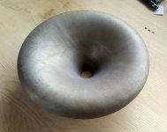
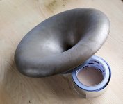
This is my 5th printed revision since downloading the file in ~mid April. This is the smaller, technically ST252, version of the ST260-30.
These are all printed in one piece facing down. I put little to no effort into cleanly removing support materials, hence the ugly. Will probably print final versions face up to make finishing easier. Loving mabats brass finish!
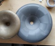
Very influenced by PatrickBateman (stolen perhaps?) on the slot port idea.
First attempts yielded poor midrange response shape and too much impact on the tweeter polars. Came up with a port layout that didn't muck tweeter polars up too badly and crash coursed on Hornresp MEH usage to solve the midrange response problems I was seeing.
This 5th version may be final but I won't get to taking polars until next week.
Attachments
In High Quality Horn Loudspeaker Systems: History, Theory and Design Bjørn mentioned an unexplored possibility to get a gradual transition in the boundary condition at the mouth by a series of holes/openings. The technique is used in some high speed train tunnels to mitigate the sonic boom problem.
In my mind this might a viable option to try when there is no need to print the entire horn but rather exchange petals on the throat part.
If anybody wants to try to overlap the horn over a midrange driver, then the work done by PK-sound is rather interesting to have in the back of the scull. COHERENT MIDRANGE INTEGRATOR (CMI)
A couple of thoughts on this:
1) Bose patented what you describe, which may be why it's not seen much. Bose has been patenting horn stuff like crazy. They're doing some interesting things with transmission lines and horns and reflectors. To me, it looks like most of the patents are intended to squeeze horns and TLs into televisions, similar to how the Bose system in Mazda's RX7 had a transmission line sub that snaked around the trunk of the car.
2) PK Sound originally ran Danley Lab Subs, and are certainly aware of the modern Danley speakers. Methinks the Trinity speakers had some inspiration from the Unity horn.
This time I will apply a proper coat of a filler/primer on the whole surface first. I think this is why there are still the seams between the parts slightly visible on the ST260.
Check out what Brinkman has accomplished, using Wood Filler on PETG 3D printed waveguides, then covered with spray paint. The finish looked fantastic.
- Home
- Loudspeakers
- Multi-Way
- Acoustic Horn Design – The Easy Way (Ath4)