Mine have a resonant frequency of about 55 Hz. Your drivers are still new and therefore it is a bit higher with yours. If you move the diaphragm back and forth with your hands a few times until the resistance becomes noticeably higher, that should be enough. Alternatively, you can also play the woofers in overnight with a 30Hz signal and relatively high excursion (3-4mm). If you place both woofers face to face and connect one of them the other way around (plus to minus and minus to plus), you almost don't hear it.
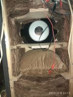
A little more damping can't hurt. I would add a little more material between the lid and the upper strut and on the rear wall.
A little more damping can't hurt. I would add a little more material between the lid and the upper strut and on the rear wall.
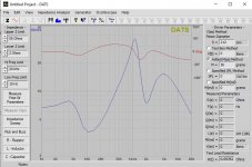
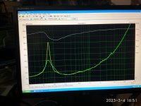
I'm thinking that the woofer impedance still looks a bit 'wobbly'? I think a good way to see what the box resonances do is to measure the woofer impedance in and out of the box and overlay the two to compare.Here is the impedance plots in the cabinet with damping material BUT no crossover connected.
Now I think that is clean ,the second impedance peak at 1.174khz is a crossover result.
EDIT: Sometimes it's even possible to enter the internal box dimensions in some 'room mode calculator' (lazy way) to find what dimension is causing the resonance at a specific frequency. I think usually the longest dimension is the most problematic, especially if the woofer is close to one end of that dimension. Can take a lot of damping to take care of that lowest resonance. Also a lot of damping on the wall behind the woofer is usually good if the woofer is playing up in the midrange.
Last edited:
What I meant is if you use the overlay function in ARTA/LIMP (you see it in the top menu) you can do one measurement out of the box, set it as overlay, and one in the box and easily see the difference, preferably with the woofer measured directly, without XO.
Usually I just have the box laid down on it's back with the woofer up when I play around with stuffing. I don't even screw the woofer in, just hold it down with my hands when I measure, and them lift it up to change the stuffing in the box, and measure again. All the time with the free air impedance as overlay to compare. Makes everything a lot quicker and easier.
Looks like there is some ripples in free air too, so maybe the damping in the box is sufficient in this case.
I will try to add some wool pillows inside the box and measure again
That I don't understand is why my measurements don't agree with yours.
Mine free to air measurements is different even from manufacturer's.
I will try the burn in procedure too.
I think that I must connect woofer directly to amplifier output without crossover for this burn in?
Is it possible that different measurement is a result that I don't use an amplifier between sound card and speaker under test?
Last edited:
I didn't take any measurements from the woofer at all, so I don't quite understand why you think our measurements differ.
When measuring, make sure the woofer is not on top of the magnet and the hole is not covered.
Do the burn in and then measure again. The resonant frequency should then be somewhat lower. You do not need the X-Over for the burn in.
When measuring, make sure the woofer is not on top of the magnet and the hole is not covered.
Do the burn in and then measure again. The resonant frequency should then be somewhat lower. You do not need the X-Over for the burn in.
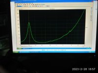
I'm referring to this measurement.
Isn't your's?
When measuring, make sure the woofer is not on top of the magnet and the hole is not covered.
Does it mean that for free to air measurement I need to place woofer vertically?
Isn't your's?
When measuring, make sure the woofer is not on top of the magnet and the hole is not covered.
Does it mean that for free to air measurement I need to place woofer vertically?
Attachments
Last edited:
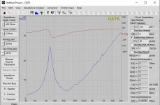
Yes, this is my measurement, but that of the complete speaker.
DATS V3 unfortunately has a problem with the GHP principle, so the measurement in the bass looks strange.
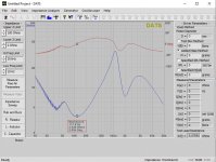
I just measured only the woofer, once with and once without Xover. I have bridged the 560µF cap here, so that DATS does not measure strange things again.
And yes, the woofer should be placed as it will later be mounted in the box.
DATS V3 unfortunately has a problem with the GHP principle, so the measurement in the bass looks strange.
I just measured only the woofer, once with and once without Xover. I have bridged the 560µF cap here, so that DATS does not measure strange things again.
And yes, the woofer should be placed as it will later be mounted in the box.
Attachments

I'm at exactly the same spot with my journey.
I'm getting the same 'asymmetry' in the impedance peak. In my case it seems that a small peak that was present from the start gets more visible. All impedance models I found and understood do not predict that.
Where is the asymmetry coming from and what does it indicate and what does it do to the sound?
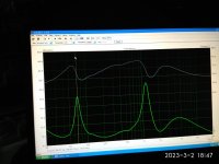
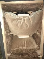
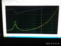
The pillow behind woofer removed.
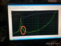
Yellow plot is before,green is after pillow removing.
I have also run a burn-in 30hz 8v RMS for 12 hours.
I can't see a difference after the burn-in.
Speaking for damping,what you prefer?
The yellow or the green plot?
Any other suggestions acceptable.
Yellow plot is before,green is after pillow removing.
I have also run a burn-in 30hz 8v RMS for 12 hours.
I can't see a difference after the burn-in.
Speaking for damping,what you prefer?
The yellow or the green plot?
Any other suggestions acceptable.
Attachments
Last edited:
It's not as obvious as I hoped. My hypothesis was that the pillows caused separate resonance chambers causing two resonance peaks. With one pillow I hoped it would just be one. Although it lowered the second one, it didn't remove it.
Here is my journey:
https://www.diyaudio.com/community/threads/efficient-2-way.380822/post-7278755
Here is my journey:
https://www.diyaudio.com/community/threads/efficient-2-way.380822/post-7278755

- Home
- Loudspeakers
- Multi-Way
- Asathor - a JBL 4367 Clone