Extending the conical contour of the cone most likely works as waveguide. In this case when the central area of the cone is obstructed by the horn, the effect seems to be dramatic, and gratefully at the problematic freuency range!
When I make the full size test baffle with curved contour, I will recess the drivers by installing them on a flat plate. Then I can test the effect of smaller but smoother coupled bevels.
When I make the full size test baffle with curved contour, I will recess the drivers by installing them on a flat plate. Then I can test the effect of smaller but smoother coupled bevels.
Making the ring even smaller in diameter? Getting closer to a MEH...Extending the conical contour of the cone most likely works as waveguide. In this case when the central area of the cone is obstructed by the horn, the effect seems to be dramatic, and gratefully at the problematic freuency range!
When I make the full size test baffle with curved contour, I will recess the drivers by installing them on a flat plate. Then I can test the effect of smaller but smoother coupled bevels.
Don't want to derail your thread but I just found this one, does not seem to have a dip.
https://www.redcatt.net/cx12f-140f.html
https://www.redcatt.net/cx12f-140f.html
These are great results - congratulations!Woofer problem solved!
Did you already do some measurements off axis to check what's happening and if it influences the tweeter off axis response?
That one seems to have the horm much closer to the cone. Someone linked earlier a coax that had a rubber band or something like that behind the edge of the horn. I
ll try to find something like that for testing!
ll try to find something like that for testing!
Nobody has mentioned 3D printing of that absorber ring yet. I shouldn't be the first since I have no experience in 3D printing. I have heard that you have to seal 3D printed horns to make them airtight and thus not transparent to sound. I can't help thinking that if you printed a ring to fill the gap at the horn edges with just the right amount of infill and didn't seal the surface you would have something very much like open cell foam.
I was just walking the dog an got a brilliant idea! The extension ring can be made of a toilet seat ring with a lid! Then one could ask friends if they want to listen to #hit music!

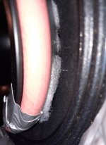
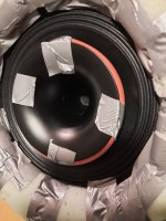
But seriously, when testing these modifications it is wise to overdo the shape, then changes in response will be larger. This time I picked a piece of 1/2" garden hose and taped a ring of it behind the horn's edge. I also tucked dacron wool behind the hose. I tested only the woofer 0-axis, and outcome is very clear.
The hose ring makes the resonance much worse! Foam extension ring rules! Notice, that in measurements Foam ring is on place in all but "nude" take.
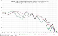
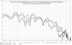


I was thinking more of having the woofer mounted from the back of baffle, creating a much smaller slot around the horn. More like a MEH...I was just walking the dog an got a brilliant idea! The extension ring can be made of a toilet seat ring with a lid! Then one could ask friends if they want to listen to #hit music!
View attachment 1125555
But seriously, when testing these modifications it is wise to overdo the shape, then changes in response will be larger. This time I picked a piece of 1/2" garden hose and taped a ring of it behind the horn's edge. I also tucked dacron wool behind the hose. I tested only the woofer 0-axis, and outcome is very clear.
The hose ring makes the resonance much worse! Foam extension ring rules! Notice, that in measurements Foam ring is on place in all but "nude" take.
View attachment 1125547 View attachment 1125548
View attachment 1125549 View attachment 1125550
Maybe try writing an email to RCF with a link to the thread could get you some feedback if they have a recommended/intended way to mount them? Could save you a lot of work. I'm thinking mounted from the back of the baffle too, which seems pretty common in PA.
On the other hand, I really like the content in your thread with some hands on experimentation! 🙂
On the other hand, I really like the content in your thread with some hands on experimentation! 🙂
Wheel trim ring, outer diameter 14" https://www.summitracing.com/parts/wvi-3000-14-1 is available from a Finnish shop too
Bicycle wheel rim 14" https://www.kunstform.org/en/salt-fraction-14-bmx-rim-14-inch-p-24864
Water pipe 2" https://www.jdpipes.co.uk/products-...ene-pressure-systems/drinking-water-pipelines
Decorative life ring https://www.amazon.com/Bilipala-Welcome-Cloth-Decorative-Nautical/dp/B01EMIOF3S
etc.
Try "pipe insulation" for small diameter round overs or "pool noodle" for larger diameter.
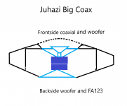
Mounting the 12" coaxial from the in-/backside of the front baffle is not easy in my case. Please see the pic in post #82, which doesn't show all the necessary bracing to make the structure hold. And the coax will be in a small subchamber. It might be possible to make a separate removable back cover for the coax box . If this was an OB, I would definitely mount it on the backside.
I must discuss this with the cabinet maker, because it seems like it will be too difficult for me anyway. We also have an open access workshop here too, if I must do them myself. And I want the speakers to be ready till the end of April, before summer cabin season!
I must discuss this with the cabinet maker, because it seems like it will be too difficult for me anyway. We also have an open access workshop here too, if I must do them myself. And I want the speakers to be ready till the end of April, before summer cabin season!
Last edited:
Nope. But I don't expect any problems off-axis or regarding horn output. I might do those during next days, but my interest is now in making a full size curved test baffle that can hold the woofer as well.These are great results - congratulations!
Did you already do some measurements off axis to check what's happening and if it influences the tweeter off axis response?
You could do a perforated smooth ring around the horn to cover the woofer section and just enough perforation to allow the midrange to come through but enough material to reduce the dip. This would of course involve some experimentation to get the ratio of perforation right. You could also apply some dampening behind the perforation to clean up the upper mids.
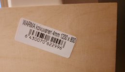
I marked the curved and sub test baffles for cutting. Bows for the curve must be marked too. Actually openings in the curved baffle should be oval, but this is just a proto and I can mod them if needed. Height 1200mm, width 800mm without curvature. Width of the sub baffle is 400mm, height 1200mm. Cutout for RCF is 288mm, for SL-12 278mm.
Tomorrow will be only -10C, next days -15 to -25C and I must work ourdoors on the terrace...
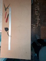
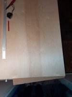
Tomorrow will be only -10C, next days -15 to -25C and I must work ourdoors on the terrace...


- Home
- Loudspeakers
- Multi-Way
- Big coaxial with RCF CX12N251
