The BJT Locanthi EF3 is good enough for me.
I'm very happy that Mr.Cordell helped me overcome my "fear" of it.
http://www.diyaudio.com/forums/solid-state/149324-self-type-3-ef-hybrid-triple-any-pointers.html
That's the thread - took me almost 4 more years to integrate that with
what H/K did with the 680/990.
Yes , one of our members actually did machine a solid copper block ,
mount 4 MT-200's , and hook up a ASUS CPU cooling unit with fan/
radiator/hoses (VERY professional). DIY at it's best !
OS
So is it true from all the comments that it's better to not worry about the large Class A using high current, instead concentrate on running Oliver's optimization. Using Re=0.22ohm for safety. Using 120mA bias for Oliver's condition and use the highest voltage rail to keep the heat to around 60W per side and call it a day?
This is getting into the grey area where you guys that have experience with real amp know better which way to go. I have no idea.
I have a nice 250W/8 class AB amp with BJT OPS running for years...... increased bias slightly beyond the minimum for distortion and reduced the Re to .11 Ohm (just paralleled the .22's). On the subjective side it also sounds clearer/cleaner BUT, I blow an OPS every 1-2 years in it. Kind of a sorry state of affairs. Move to FETs for OPS seems to work better over-all.
THx-RNMarsh
Last edited:
I have a nice 250W/8 class AB amp with BJT OPS running for years...... increased bias slightly beyond the minimum for distortion and reduced the Re to .11 Ohm (just paralleled the .22's). On the subjective side it also sounds clearer/cleaner BUT, I blow an OPS every 1-2 years in it. Kind of a sorry state of affairs. Move to FETs for OPS seems to work better over-all.
THx-RNMarsh
I increase the bias current of my Acurus from very cold bias to 100mA each stage. It has 4 stages, it's quite an improvement on the sound. that's the reason I want to keep the bias high.
I did not even parallel the resistor to lower the Re. It's stock with 0.5ohm, I know I violated the Oliver's condition, but I tell you, it sounds much better since. Problem is the amp has +/-80V rail, it's getting very warm with 100mA bias per stage. that's the reason I am so incline to go lower rail and higher current.
Alan,
If your devices are getting warm but are operating in the SOA then what is the real problem, is it just an unrealistic fear? And why would you think that you would have to make such a drastic change from 80V rails all the way down to 25V rails? It doesn't seem to make sense. I don't know why you don't just try what Bob and some of the others have told you, perhaps they actually do know what they are talking about. Use the Re resistor values that Bob has told you work well, you are falling into the audiophile mistake of thinking everything must be on the limits, you are just pushing yourself into a corner. Set the bias at a reasonable level and use stable values for long term usage. There are so many high quality amps that just run for years, perhaps you will have to change an electrolytic cap in twenty years but do you really want to end up as Richard was just saying and every couple of years need to rebuild an amp or have one that just works?
If your devices are getting warm but are operating in the SOA then what is the real problem, is it just an unrealistic fear? And why would you think that you would have to make such a drastic change from 80V rails all the way down to 25V rails? It doesn't seem to make sense. I don't know why you don't just try what Bob and some of the others have told you, perhaps they actually do know what they are talking about. Use the Re resistor values that Bob has told you work well, you are falling into the audiophile mistake of thinking everything must be on the limits, you are just pushing yourself into a corner. Set the bias at a reasonable level and use stable values for long term usage. There are so many high quality amps that just run for years, perhaps you will have to change an electrolytic cap in twenty years but do you really want to end up as Richard was just saying and every couple of years need to rebuild an amp or have one that just works?
I don't know, I am not familiar in calculating the heatsink.
The 80V is the Acurus amp I have. I am building a new amp. After I increase the bias to 100mA on the acurus, it sounds better but getting hot. So no matter whether I just follow Oliver's condition by lowering the current, I want to keep the voltage lower so the amp doesn't get that hot. I don't need 200W like the Acurus.
I got the message loud and clear, I am planning to lower the current, use 0.22ohm as suggested and satisfies the Olivers by adjusting between 120mA to 140mA per stage.
Last edited:
Alan, most DVM's will have a capability to measure temperature if you have a simple thermocouple. You could actually check and see how hot you are actually running. I have seen the information for the temp rise in the data sheets for the power transistors. You can use that information with some of the heatsink companies data to calculate the needed heatsink size needed. Make sure you use a good quality electrical grade grease between the output devices and the sinks. don't forget that any insulators between the devices and the sinks have to be considered.
I don't know, I am not familiar in calculating the heatsink.
The 80V is the Acurus amp I have. I am building a new amp. After I increase the bias to 100mA on the acurus, it sounds better but getting hot. So no matter whether I just follow Oliver's condition by lowering the current, I want to keep the voltage lower so the amp doesn't get that hot. I don't need 200W like the Acurus.
I got the message loud and clear, I am planning to lower the current, use 0.22ohm as suggested and satisfies the Olivers by adjusting between 120mA to 140mA per stage.
It may be worth experimenting with you Acurus amplifier to see why raising the bias level improved the sound.Was it the rise in output device current, or was it the rise in driver current or another device? Were the drivers not biased properly before, and now they are fully class A?
Raising rail voltage can affect sound quality at lower volumes, depending on the amplifier and the speakers it is driving. Extra voltage can help reproducing those little nuances that change a sound from good to amazing. Personally I wouldn't think of using anything under 50V rails and I'm running very efficient speakers. 80V as in your Acurus is extreme and would make it harder to maintain SOA.
Last edited:
call it a day?
Remaining option would be dynamic rails on demand.
Class A all the way, for a class AB meal ticket.
=> 1024W class A+, Glen Kleinschmidt.
(Threshold SA/12e, 250W class A, BJT output stage. Though technically class A only till 5.5A out)
You got the message but it is not clear..............I got the message loud and clear, I am planning to lower the current, use 0.22ohm as suggested and satisfies the Olivers by adjusting between 120mA to 140mA per stage.
Using 26mVre as the maximum, which includes the drops inside the transistor and before the transistor, then using I=V/R the maximum bias current per output pair will be 0.026mV / 0.22ohms <=118.2mA
It is likely that the actual optimum will be between 80% and 90% of that maximum. i.e. when you measure the crossover distortion and optimise Vre to achieve minimum crossover distortion your output bias is likely to be between 106mA and 95mA
The total output bias for a 5pair stage will be around 0.5A which at +-45Vdc results in ~45W of heatsink dissipation. Add on a little for the driver dissipation and you are well below a guesstimated 60W target.
Like I said earlier, build using your 30-0-30Vac transformer and measure and listen. Then decide whether you need to buy a new transformer.
A transformer swap is probably one of the easiest jobs you can do.
I increase the bias current of my Acurus from very cold bias to 100mA each stage. It has 4 stages, it's quite an improvement on the sound. that's the reason I want to keep the bias high.
I did not even parallel the resistor to lower the Re. It's stock with 0.5ohm, I know I violated the Oliver's condition, but I tell you, it sounds much better since. Problem is the amp has +/-80V rail, it's getting very warm with 100mA bias per stage. that's the reason I am so incline to go lower rail and higher current.
Alan,
With regard to heat and heat sink temperature, I try to put things in perspective by considering heat sink temperature that is acceptable. First of all, if you want to go by the federal standard, your amplifier should be able to do 1/3 power into 8 ohms for 1 hour without over-heating. 1/3 power is theroretically where max dissipation occurs. This can be a tough test, but also keep in mind that such an amplifier will get hotter into a 4 ohm load. I often go for max of 1/8 power for the criteria rather than 1/3 power. This test seems a bit more reasonable.
Also, keep in mind that a great many amplifiers will cut out when the heat sinks reach 70C. Your output stage SOA should thus be adequate for the transistor cases to be somewhat over 70C to take into account thermal resistance of the washers.
Moreover, it is really desirable to have the heat sinks stay under 60C under any expected user condition, since 60C is the temperature at which you can keep your finger on the heat sink for several seconds.
When you look at it this way, you have perspective on how hot is OK for the amplifier to run at idle. Idle heat sink temperature is usually not a problem. In fact, if idle heat sink temperature is warmer, there is potentially less thermal swing when the music gets to extended passages where average dissipation increases substantially.
Cheers,
Bob
60C is the temperature at which you can keep your finger on the heat sink for several seconds.
~ 2 seconds.
(epidermis numbers for aluminum : indefinite for 44C, 10s at 50C, less than 5 seconds at 55C)
The BJT Locanthi EF3 is good enough for me.
I'm very happy that Mr.Cordell helped me overcome my "fear" of it.
http://www.diyaudio.com/forums/solid-state/149324-self-type-3-ef-hybrid-triple-any-pointers.html
That's the thread - took me almost 4 more years to integrate that with
what H/K did with the 680/990.
Yes , one of our members actually did machine a solid copper block ,
mount 4 MT-200's , and hook up a ASUS CPU cooling unit with fan/
radiator/hoses (VERY professional). DIY at it's best !
OS
I like the Locanthi EF3 partly because the pre-driver and driver stay in class A.
I usually put the driver and predriver on their own board-mounted heat spreader, rather than one or both on the main heat sink. I use 2 bias spreaders, one on the main heat sink and one on the on-board heat spreader. The driver and pre-driver are then not subject to much thermal change and are tracked very well. This overcomes the thermal stability issue that results from a full 6 Vbe in series with the EF3 Triple.
I also always center-tap the emitter resistor that biases the driver. This makes it easy for some testing and measurement. If the feedback is taken from this center tap rather than the output, distortion of the IPS-VAS can largely be measured without the output stage. One can, of course, go further back by one stage by center-tapping the pre-driver emitter resistor. During the initial build, the loop can be closed without the output transistors, if desired. Finally, if you put a distortion analyzer on this node when the loop is closed from this node, you can see a very decent approximation of the open-loop output stage distortion.
Cheers,
Bob
It may be worth experimenting with you Acurus amplifier to see why raising the bias level improved the sound.Was it the rise in output device current, or was it the rise in driver current or another device? Were the drivers not biased properly before, and now they are fully class A?
Raising rail voltage can affect sound quality at lower volumes, depending on the amplifier and the speakers it is driving. Extra voltage can help reproducing those little nuances that change a sound from good to amazing. Personally I wouldn't think of using anything under 50V rails and I'm running very efficient speakers. 80V as in your Acurus is extreme and would make it harder to maintain SOA.
The Acurus was bias cold. I don't remember the voltage across the Re, that was before I even read about Oliver's condition. I am sure it's way lower than 26mV for 0.5ohm. It must be like 10 to 15mV. Yes, it was biased cold. All there channels were like this, so I don't think it drifted off through time. The Acurus used to run cold, I mean you can run for hours and you barely feel the heatsink. It's no where close to Class A right now. It's only has about 1W of Class A. Because of the 80V rail, it's too hot already.
Yes, I do have to admit that increasing a little improved the sound already, but I keep increasing to 100mA. Kind of little is good, more is better!!! That's my thinking on my new design.
I can argue about more current in Class A is better or what not, but I never complete a single stereo amp. So when you guys start saying that increase the Class A region does not improve the sound. I have to take that at heart.......for now!!!!
I started building two more OPS boards planning to go higher current for comparison in the future. I am going to order 0.18ohm and run higher current on the new set. If I hear improvement, then I'll stick tongue to you guys!
!
Last edited:
You got the message but it is not clear.
Using 26mVre as the maximum, which includes the drops inside the transistor and before the transistor, then using I=V/R the maximum bias current per output pair will be 0.026mV / 0.22ohms <=118.2mA
It is likely that the actual optimum will be between 80% and 90% of that maximum. i.e. when you measure the crossover distortion and optimise Vre to achieve minimum crossover distortion your output bias is likely to be between 106mA and 95mA
The total output bias for a 5pair stage will be around 0.5A which at +-45Vdc results in ~45W of heatsink dissipation. Add on a little for the driver dissipation and you are well below a guesstimated 60W target.
Like I said earlier, build using your 30-0-30Vac transformer and measure and listen. Then decide whether you need to buy a new transformer.
A transformer swap is probably one of the easiest jobs you can do.
Yeh yeh yeh!!!
I decided not to buy for now. I already build the prototype on a wood board. I already put in two 24V switching supply for simplicity. I just going to run lower power on the prototype. I don't need the transformer until I finish testing the prototype and ready to build into the real chassis. I don't want to drill a single hole on the nice chassis until I am ready.
It's a lot of work to even start testing. I am building the preamp right now. I don't even have another one for testing!!! I just sent out the pcb for that. It's a long process to even get started. It really test my patience. I can only looking at all the pcbs and talk here right now!!!
When comes to audiophile, I have no experience, I have to trust you guys when all of you say there will be no improvement even if I increase the Class A region by increasing the bias current. But I definitely going to crank up the current later to listen and see whether I can hear any improvement. I might still stick tongue to you guys if I can hear improvement
Listen? Yes. Measure? I don't have a spectrum analyze like when I was at work. I have no idea yet how to do it at home. do you buy a ADC card for the computer? I use laptop, what do you guys do?
Last edited:
I like the Locanthi EF3 partly because the pre-driver and driver stay in class A.
I usually put the driver and predriver on their own board-mounted heat spreader, rather than one or both on the main heat sink. I use 2 bias spreaders, one on the main heat sink and one on the on-board heat spreader. The driver and pre-driver are then not subject to much thermal change and are tracked very well. This overcomes the thermal stability issue that results from a full 6 Vbe in series with the EF3 Triple.
I also always center-tap the emitter resistor that biases the driver. This makes it easy for some testing and measurement. If the feedback is taken from this center tap rather than the output, distortion of the IPS-VAS can largely be measured without the output stage. One can, of course, go further back by one stage by center-tapping the pre-driver emitter resistor. During the initial build, the loop can be closed without the output transistors, if desired. Finally, if you put a distortion analyzer on this node when the loop is closed from this node, you can see a very decent approximation of the open-loop output stage distortion.
Cheers,
Bob
Wow. Bob - you just described the H/K Vbe , AND the way I initially test run a new EF3.
I've had members criticize how I recommend initial tests - I just call it
"loopback" (from the drivers - below 1).
The Vbe (below 2) , as you describe it .... is real good . A tiny bit of
NTC >55C.
MJE340 seems to track MJL/NJW ON devices nearly perfectly. BDxxx
or a 3503 , not as well. I'm sure you could tweak the R values , but 340's
are easy to source.
The only better thermal solution is to replace the Main Vbe (in the schema)
with two thermaltrak diode junctions , H/K did this in the 21'st century (HK990).
I chose the 20'th century , so builders can use ON/Sanken BJT (or
IRFPxxxx - LED in Vbe).
Thanks for getting me going 4 years ago , EF3 is the standard now.
OS
Attachments
Alan,
With regard to heat and heat sink temperature, I try to put things in perspective by considering heat sink temperature that is acceptable. First of all, if you want to go by the federal standard, your amplifier should be able to do 1/3 power into 8 ohms for 1 hour without over-heating. 1/3 power is theroretically where max dissipation occurs. This can be a tough test, but also keep in mind that such an amplifier will get hotter into a 4 ohm load. I often go for max of 1/8 power for the criteria rather than 1/3 power. This test seems a bit more reasonable.
Also, keep in mind that a great many amplifiers will cut out when the heat sinks reach 70C. Your output stage SOA should thus be adequate for the transistor cases to be somewhat over 70C to take into account thermal resistance of the washers.
Moreover, it is really desirable to have the heat sinks stay under 60C under any expected user condition, since 60C is the temperature at which you can keep your finger on the heat sink for several seconds.
When you look at it this way, you have perspective on how hot is OK for the amplifier to run at idle. Idle heat sink temperature is usually not a problem. In fact, if idle heat sink temperature is warmer, there is potentially less thermal swing when the music gets to extended passages where average dissipation increases substantially.
Cheers,
Bob
Thanks Mr. Cordell.
One question about the MJL1302/3281. The SOA graph only show down to 1 second, they don't have SOA of DC graph. How do you calculate the SOA?
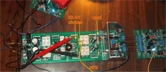
Heatsink USA 300mm X 140mm . They approximate .85 C/W for 75mm.
So I should be @.4x C/W with the 140mm.
I run 65ma per device which runs off 72V rails. I either calculate 4.8W or
9.6W depending on whether I factor 72/144V.
48W or 96W (5 pairs) ......
In the real world , the extrusion goes up to 42-45C in a 20C room. This
22-25C rise corresponds to the 48W calculation. Am I doing it right ?
The real heatsink always stays under 50C , even with heavy use.
I also have my sub amp 3X pair Sanken @ 100ma. Same wattage/same C/W.
A bit hotter driving bass (1/3 power for sure). 55C+ is attainable.
OS
The SOA graph only show down to 1 second, they don't have SOA of DC graph.
(how does one call a pulse with a duration of 1 second)
you are concerned about temperature. Measure the temperature. Your fingers are a better measuring instrument than your ears...................Listen? Yes. Measure?
easy.(how does one call a pulse with a duration of 1 second)
You arrange for the current pulse to last 1second.
- Home
- Amplifiers
- Solid State
- Bob Cordell's Power amplifier book