Second version vs First version impressions:
Being a great fan of Bob's 1st version of Designing Audio Power Amplifiers, I was curious if upgrading to the 2nd version was worth the outlay of $80. Not able to find the answer using Google, I took the plunge and ordered the 2nd version to find out for myself.
I have not read the whole book yet, but have been very pleased so far. I am finding that, besides the new chapters in V2, the chapters from the 1st version seem to have been given a thoughtful going over for clarity and completeness. Some questions that had popped into my mind during my multiple readings of the 1st version are now finding answers laid out in the 2nd version.
Since I am preparing to begin design of my latest amplifier project (and first complete amplifier from AC line cord to output, not just audio amplifier stage PCB), I am pleased to say that my ~$80 spent on upgrading from Cordell V1 to V2 was indeed money well spent. Bob's book V2 is the perfect compliment to Douglas Self's latest book on amplifiers, V6, for those looking to design amplifiers with a deep understanding of not just the "how", but the "why" aspects of audio amplification.
Well done Bob.
Simple question
Hello and you're welcome Bob.
I have a simple question as I work thru version 2 of your wonderful book on amplifiers.
In the chapter on Noise (chapter 5, pg 124) you state that the ENBW of 500kHz bandwidth with a single pole rolloff is 690 kHz. If the EBNW factor for a 1st order filter is 1.571 (Table 5.1), shouldn't the EBNW be 785.5 kHz?
Also, I've noticed a few typos in the book (schematic component reference number mistakes), but you've probably already noticed them.
Thanks and best wishes, Mike
Hi Mike,
I'm sorry to be slow in getting back to you. I've looked for the origin of the noise calculation of ENBW of 690 kHz from an amplifier with a first-order 500-kHz high-frequency roll-off as mentioned on page 124, and have not been able to find it. The 690 kHz number appears to be an error. It may have been derived from an amplifier simulation in which somewhere along the line there was an error, or there was a second pole in the closed-loop response that I had not seen.
Thanks again for bringing that to my attention. I welcome any additional feedback you have on any errors in the book.
Cheers,
Bob
Reply
No worries Bob. I can note any typos as I find them, I do notice the odd one here and there that mostly are component reference numbers not agreeing with associated schematics. Just let me know
I've made it up to chapter 12 (Output Stages) and I have to say, I am blown away by the increase in material compared to Edition 1. I especially appreciate the new material on the areas which I had been planning to investigate myself such as TMC (my preferred compensation method) for instance. This will save me much time experimenting with and simulating C1-C2-R ratios now that you've done the heavy lifting for me!
I also appreciate your elaboration on the influence of output power level on the optimal level of bias voltage as well as it's effect on the distortion harmonics. I have noticed that myself while trying to optimize bias for new amplifiers, and been left pondering what level of output power to use. Least I now know this issue wasn't just my imagination (or bad measurement techniques).
You've almost talked me into including DC servos in my next amplifier. Component matching has always allowed me to hit <5mV DC offset, but has stuck me with electrolytic caps and the required Rin = Rfeedback issue as you point out. Not yet sold on a JFET IPS. Still partial to a pair of degenerated ZTX951's with heavy tail current - the Self influence.
The length of the "improvements laundry list" in chapter 4 was most impressive. I'm gonna need a lot more PCB real estate going forward!
Best wishes, Mike
Last edited:
I saw the Klever Klipper on the Neurochrome site (and poking around on diyaudio, this appears the most appropriate place to discuss it) and saw how the circuit begins distorting at a "relatively low" power level (distortion starts going up around a third of max power output) versus regular clipping. I'm thinking that two Schottky diodes with their lower forward voltage (and presumably sharper knee) might work better here. The BAT54S conveniently has two series diodes in one package.
Would Schottkys "sound better" here, or would the sharper knee make for a harsher sound when the distortion finally does kick in? Also, it seems one can adjust knee sharpness by adding diodes of either type in series.
Has the "sharpness" of such pre-power-amplifier limiters been discussed before, in this thread (sorry, I haven't read much here) or elsewhere?
Hawksford cascode + EF3 is the "bomb".
Solves nearly every problem.
Clipping with flashing leds at overload is cool . Lighting up a toaster oven
with that clipping amp is even cooler.
Thank you , Mr. Cordell ... for leading me to the EF3.
"Troubles with triples" thread.
No way back ,now - love them 3-4mA VAS IPS's.
DIYA is about to become "precision EF3" with micro protection, variable bias
(micro) and modular options. AB will beat A (Pass) .
PS - AB is A "firstwatt".
OS
Bob Cordell
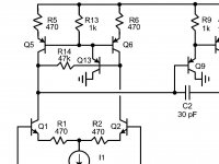
Anyone tried building up an amplifier using Cordell's complemetary diff + current mirror + VAS.
Refer to page 136-139. I built this circuit physically. Of course in LTSpice it works perfectly.
Changed the tail current to 2mA per side.
Changed R5 and R6 to 348R.
Changed R1-R4 to 113R
My VAS uses cascodes at each side using a blue LED as the common base bias voltage.
Simple triplet on the output stage.
The problem exists whether the triplet is engaged or not.
The voltage at the base of Q9/Q11 is much higher than that at the collectors of Q2/Q4.
In Spice they are the same.
Running 16mA up my VAS
Is this "Figure 7.9 Complementary differential input stage with current mirror loads suffers quiescent bias instability." ??
I'd guess you have quiescent bias instability.
I don't know what point in changing Cordell's values. Using book values, "collectors of Q2" is 1.1V down from the rail. "base of Q9" (collector of Q1) is..... undefined. It could be 0.6V from the rail or a hair below zero volts from common. Q10 could be flowing dead-zero or 2 Amps (@44V rail).
IF it were happy (but we have not caused this to be so) and magically cause 16mA in Vas, then Q9 Base would be 1.55V from rail. I do not know what "much higher" you are seeing. 400mV? 4V? -4V??
Or did you get to the one with R14? (I missed that at first.) You do not say what you changed R14 to. It may matter. I'm also overlooking this LED stuff.
Attachments
I'd guess you have quiescent bias instability.
As it says in the caption ;-)
Jan
Cordell
I refer to figure 7.10 specifically.
I configured this as just a class A preamp. That is just the VAS with no further followers. The VAS collectors are connected together.
It makes no difference what tail current I choose, adjusting the mirror's emitter degeneration resistors to suit, the circuit does not always have equal voltage at the collectors of the diff pairs.
There is no bias instability as it is configured as a class A preamp.
Cordell
Referring to fig 7.10.
Volt drops across R5 and R6 are the same.
The volt drop from +Vcc to collector Q2 is as expected and calculated.
The volt drop from +Vcc to collector of Q1 is NOT the same as that for Q2.
There is no circuit mechanism that can predict this or am I missing something.
Referring to fig 7.10.
Volt drops across R5 and R6 are the same.
The volt drop from +Vcc to collector Q2 is as expected and calculated.
The volt drop from +Vcc to collector of Q1 is NOT the same as that for Q2.
There is no circuit mechanism that can predict this or am I missing something.
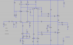
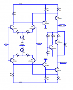
Is this the circuit you are referring to?
Maybe you could post your circuit.
BTW: it is normal that you have different voltage drops.
Personally I'm looking at the input voltage and the output voltage I don't look at voltages inside the amp, but are looking at the currents.
Maybe you could post your circuit.
BTW: it is normal that you have different voltage drops.
Personally I'm looking at the input voltage and the output voltage I don't look at voltages inside the amp, but are looking at the currents.
Attachments
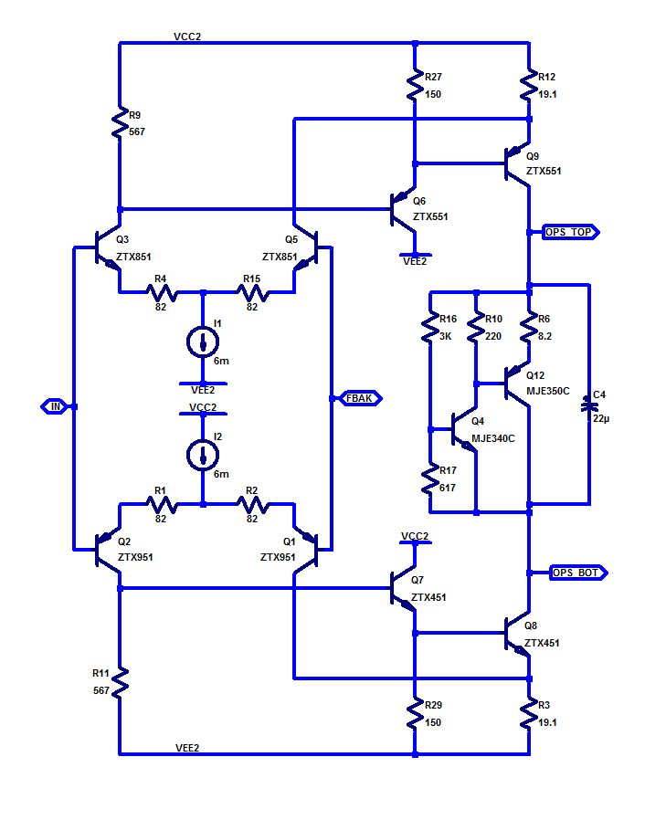
Just say no to complimentary LTP.
The problem originates in the fact that the offset voltage of the NPN LTP and the PNP LTP are unlikely to be exactly the same so they drive the two VAS away from each other and to too much or too little VAS current. Perhaps if the they had separate feedback from the OPS emitter resistors, this could work, but you would need a pot instead of two LPT degeneration resistors on one side, which would adjust the one of the offsets to match the other and set the VAS current and the output idle bias. But then you have a problem under signal where the difference between the two LTP becomes a difference at the OPS and the idle current rises as you slew away from zero output.
No, complimentary LTP is just a bad idea. Using resistors instead of a current mirror works but not well, the VAS has to have degeneration. I do like the P-P VAS driven from a single LTP where the combined VAS current is a constant current.
Attachments
Cordell
In order to define the current through Q9 and Q11 the volt drop from the +Vcc rail to Q1 collector (-Vcc rail to Q7 collector) MUST 100% be defined both in calculation and in practice.
This affects the volt drop across R9 and R11 and these ultimately define the volt drop across R10 and R12 and thus the VAS standing current.
I have built both Bob's circuit and mine and they exhibity the same issue that VAS current is not definded.
I understand fully the volt drop across say R6 as 50% diff current x 470R.
I also understand the 2 x Vbe drops to get to the voltage at Q2/Q8's collectors.
But there is nothing which allows you to calculate the voltage between the rails and Q1 and Q3's collectors.
A complimentary LTP is not a bad idea, but you need to know how to handle it. As Bob Cordell already said: "the VAS bias current in this circuit is undefined".[...]
No, complimentary LTP is just a bad idea. Using resistors instead of a current mirror works but not well, the VAS has to have degeneration. I do like the P-P VAS driven from a single LTP where the combined VAS current is a constant current.
Many people, even a guy like Randy Slone don't realise this. Have a look here.
What you simply need is a "common mode control loop" (CMCL), comprising four additional trannies.
Cheers,
E.
I used resistive loading in my original 200 W amp from 2007 and then again in 2012 on the e-Amp. Both were complementary LTP designs and I had no balance issues. With mirror loaded LTP’s, , the balance issue is exacerbated so you need a CMCL. If the thought of 4 extra trannies fills you with trepidation, you can always slightly unbalance one of the pairs for a penalty of a few ppm.
Do the Lender trick with the first stage to second stage connection. Voila, you get a push-pull VAS with well defined bias currents in both stages. You also get more gain than either resistor loads or folded cascode. (however less gain than a current mirror)
Click on the image to see it full size and undistorted:
_
Click on the image to see it full size and undistorted:
_
Attachments
- Home
- Amplifiers
- Solid State
- Bob Cordell's Power amplifier book