Some QCC5144 modules have built-in antenna, there are also QCC3044 or QCC3050 (only QCC5151 is better than this one) which are cheaper. They use BTM544/344/350 modules which are compatible with BTM525 (only some PIO are different, easy to fix within firmware).
QCC3008 actually has 6 dB less signal strength than QCC5144, while QCC5125 is something in between.
All 51 and 34/35 series chips can be easily programmed via USB (Windows only, unfortunately, VirtualBox won't work).
I have QCC5144 board (with PCB antenna) right in my hands and just checked: it works fine (with headset, not earbud firmware) for about 7 meters through 3 concrete walls with aptX Adaptive. If I turn myself around then signal seems to be blocked by my body at this distance, but this is kinda expected.
And you don't actually need to make a PCB as some modules have 2 mm pin header.

Adding second antenna in parallel is generally a bad idea, but you can search how to add external antenna to Raspberry Pi Zero W.
You may also want to take a look at reference schematic (there is an external antenna connector).
QCC514x/2x and 304x/305x series have VDD_PADS which may be powered with 1V8/3V3 (maybe other voltages are fine too, but I haven't checked).
QCC3008 actually has 6 dB less signal strength than QCC5144, while QCC5125 is something in between.
All 51 and 34/35 series chips can be easily programmed via USB (Windows only, unfortunately, VirtualBox won't work).
I have QCC5144 board (with PCB antenna) right in my hands and just checked: it works fine (with headset, not earbud firmware) for about 7 meters through 3 concrete walls with aptX Adaptive. If I turn myself around then signal seems to be blocked by my body at this distance, but this is kinda expected.
And you don't actually need to make a PCB as some modules have 2 mm pin header.
Adding second antenna in parallel is generally a bad idea, but you can search how to add external antenna to Raspberry Pi Zero W.
You may also want to take a look at reference schematic (there is an external antenna connector).
QCC514x/2x and 304x/305x series have VDD_PADS which may be powered with 1V8/3V3 (maybe other voltages are fine too, but I haven't checked).
can someone help me how to get spidff input working on a csr8675?
i got the tinysine module and really need the spidff input but I dont know how to get it to work..
Edit: I found that i need to use a unused odd PIO number .. wich can be 3. but As im new to this.. Do I need to add a resestor to the input?
i got the tinysine module and really need the spidff input but I dont know how to get it to work..
Edit: I found that i need to use a unused odd PIO number .. wich can be 3. but As im new to this.. Do I need to add a resestor to the input?
Last edited:
Hi @all!
I am making wooden wireless headphones based on the BTM308-C module which has QCC3008 chip on it. This thread and youtube videos of a user darieee were a big help in understanding how this chip works and and how to bend it to your will, so to speak") .
.
I plan to document the process of making the headphones in as series of the blog posts where I would go over mechanical design, PCB design and firmware design (how to setup ADK, what things I had to change, general overview how everything works and so on).
There is some concern about the last part: firmware, that is ADK, PS Tool, source code and all documentation that comes with it, is proprietary.
I believe that Qualcomm would not be happy that somebody is talking about that, from a legal perspective. I am kinda surprised that darieee still has his dropbox up and available, I would expect that it would be taken down by now.
Does Qualcomm not care about its IP to be distributed like that? Or they kinda accepted the fact that their tools are going to be leaked on some chinese websites?
Thanks for any reply!
I am making wooden wireless headphones based on the BTM308-C module which has QCC3008 chip on it. This thread and youtube videos of a user darieee were a big help in understanding how this chip works and and how to bend it to your will, so to speak
.I plan to document the process of making the headphones in as series of the blog posts where I would go over mechanical design, PCB design and firmware design (how to setup ADK, what things I had to change, general overview how everything works and so on).
There is some concern about the last part: firmware, that is ADK, PS Tool, source code and all documentation that comes with it, is proprietary.
I believe that Qualcomm would not be happy that somebody is talking about that, from a legal perspective. I am kinda surprised that darieee still has his dropbox up and available, I would expect that it would be taken down by now.
Does Qualcomm not care about its IP to be distributed like that? Or they kinda accepted the fact that their tools are going to be leaked on some chinese websites?
Thanks for any reply!
You can download ADK 4.0.1 here: CSR最新 ADK4.0.1 - Qualcomm(CSR)专区 - 我爱蓝牙网 - 52Bluetooth - 最具人气蓝牙技术交流网站 - Powered by Discuz!
There are other versions there too, use search to find what you need
There are other versions there too, use search to find what you need
Hello everyone,
I'm using the adk 4.4.0.21 for 8670 chip and I would like to use aptx, but I can't find the codec addon.
I have the 4.3.1.5 aptx codec addon but I'm not sure if it's compatible.
Could someone help me to find the 4.4.0.21 aptx codec addon please?
Thank you all.
I'm using the adk 4.4.0.21 for 8670 chip and I would like to use aptx, but I can't find the codec addon.
I have the 4.3.1.5 aptx codec addon but I'm not sure if it's compatible.
Could someone help me to find the 4.4.0.21 aptx codec addon please?
Thank you all.
I'm working on transplanting LDAC to QCC5144. There is an open-source decoder library on GitHub. Does someone want to take part in it? PM me if so. I'm now stuck at studying AAC decoder library for QCC5144, it's quite huge and some parts are written in assembly language.
Based on information on Chinese forums, QCC5125 version would cost 10K$ + 0.5$/device and works only with companies. This looks overpriced and it's also not suitable for QCC5144. Maybe they will be more accommodating after it will be easier to access for ordinary people.
Based on information on Chinese forums, QCC5125 version would cost 10K$ + 0.5$/device and works only with companies. This looks overpriced and it's also not suitable for QCC5144. Maybe they will be more accommodating after it will be easier to access for ordinary people.
Can someone here help me out a bit regarding TWS? I'm just trying to pair 2 CSR8675's together.
I saw TehSiggis posts, but it's not enough info and i couldn't figure it out using the docs so far...
So i have the SPI programmer, and i've read a lot of documentation and i know that in order for TWS to work at all
1. the firmware must support it (cflags must be enabled at build time)
2. the DSP code must support it (i didn't explicitly add any and universal frontend doesn't allow me to connet so i think there is none(?) running, does that mean this doesn't matter?)
3. the device must be configured accordingly in ADK config tool
So i built the sink code in xIDE with TWS enabled and in ADK config tool i enabled it, configured peer device support very leniently (GIAC, no service uuid, no device id, unlock state machine), then in TWS page set the qualification check boxes +reserve link.
Then i configured the key events for a very simple setup (i set the VOL- and VOL+, which are PIO1 and PIO2 respectively on the PCB i got, to Peer Session Inquire and Peer Session Conn Disc)
I also ensured there was some audio feedback configured in the audio events.
I hooked up some dupont wires to the button + keycom terminals on vol- and vol+ sides on both devices.
However, no matter how i configure the device in ADK config tool, i never get any audio feedback, and when i run the devices in debug mode with vmdebuglogger, i cannot see a single event indicating that the device is entering pairing mode or that they are trying to establish a session.
As a side note, the sink application generated by the xIDE build (I'm using ADK 4.2 i think, it's a build from 22.05.17) seems a bit odd to me also, when i run it on my CSRs, aptX and aptX HD are available (enabled in properties), but whenever i try to play audio with them enabled, the sink panics and the device restarts. Should i use a different ADK version?
Sorry I cannot offer much practical help, but I know that TWS definitely works if you just use the default sample code and follow the instructions in the manual (it has been a long time since I did it so I don't have all the details now, but I have seen that it works using default code). Try using ADK 4.1 or 4.0. I remember having trouble with ADK4.2 on a different project.
You might have to change some pskey settings in the sink configuration tool if you are using a custom board. If you are using development board I think there is a button you need to long press in the master and slave boards, after which they will detect and pair themselves. There is a tone feedback when TWS pairing happens (not a speech feedback I think).
You might have to change some pskey settings in the sink configuration tool if you are using a custom board. If you are using development board I think there is a button you need to long press in the master and slave boards, after which they will detect and pair themselves. There is a tone feedback when TWS pairing happens (not a speech feedback I think).
It seem I've spoke too soon about the sub out. It is possible to have all 3 outputs, but you would need to either connect the sub wirelessly with another bt module (not tested) or do it like you describles. You can also do it the other way arround, DAC for R, L and use the I2S for the sub... either should work.
Thanks!
I've had no problem with the GAIA app.
I don't know what firmware your bt module is running, but there is an option for enable the GAIA "protocol"... also, you are using the CSR8675 or the CSR64xxx? It does not work with older models like the CSR8635, CSR8645...
Yes, you can choose what to route through the DSP in the CVC tool, including I2S, analog in/out.
Many ways, depends on the amplifier, it it has LOW og HIGH logic for the mute. You can chose any GPIO. There is a setting for MUTE, so that the module will pull it high when the amplifier is muted. For the TPA311x you have to pull MUTE LOW. So an easier way is to connect it with a 1k to one of the LED outputs. Then use the "A2DP steaming" settings under LED events. This will mute the amplifer when you're not streaming music.
I have no clue, sorry. It could be done if you wrote your own code, but that's way above my knowlage.
No idea. Don't think so. Same answer as the one I gave above.
thank you. So can I install a bluetooth module with SD/FAUZT and MUTE enabled?
Sorry I cannot offer much practical help, but I know that TWS definitely works if you just use the default sample code and follow the instructions in the manual (it has been a long time since I did it so I don't have all the details now, but I have seen that it works using default code). Try using ADK 4.1 or 4.0. I remember having trouble with ADK4.2 on a different project.
You might have to change some pskey settings in the sink configuration tool if you are using a custom board. If you are using development board I think there is a button you need to long press in the master and slave boards, after which they will detect and pair themselves. There is a tone feedback when TWS pairing happens (not a speech feedback I think).
thanks for the heads-up.
However i can not for the life of me find the documentation necessary for this, i've looked through pretty much all of the PDFs now, the only relatively useful one is the peer device configuration guide but even that isn't sufficient.
I've now started looking at the actual sink code and switched all the internal debug flags on. There i can now see that the devices do try to pair but fail eventually.
The key error i'm seeing is this:
INQ: Timeout - Wait for SLC Complete
Don't know what SLC means exactly but it seems like the master is failing to connect to the slave, with a timeout. not more info than that, but from my initial looks into how it works it seems like there are some assumptions that were made that lead to no device ID filtering + no QTIL UUID filtering being a combination for peer device pairing that straight up doesn't work. (But i can't find the docs to confirm this)
As a side note, the tinysine firmware does work, but after looking through its configuration, it's not using actual TWS but broadcast audio, which i don't want.
And also after pairing the sink code panics on the slave after restarting the device for some strange reason...
Ok so i finally got it working:
- Restored to stock firmware the CSR's came with initially (which was based off ADK 4.2 it seemed because i could only use config tool from 4.2)
- in xIDE: configured sink application for TWS + imported codecs + also configured them for TWS configurations, built and flashed it using BlueFlash
- in PSTool, ensure they have different BT address endings (+ friendly names just to be sure)
- in config tool:
- ensure correct button translation mappings + configure user events for Peer ConnDisc + Inquire respectively that map to some buttons
- start master, pair with an AG, go into inquiry mode
- start slave, go into conndisc mode. (this is opt. i think but i also triggered an a2dp open peer event)
However, here's the strange thing: This didn't work for ADK 4.3, and i think it's because of corrupted PS state.
So, can someone tell me what the correct procedure for migrating to a different ADK version is?
in my case, i just flashed the tinysine build to get the PS state and then flashed the 4.3 sink application on top of that.
When i flash to 4.3 sink from my 4.2 stock firmware (or delete the persistent store in BlueFlash first), the sink panics and won't start.
Debugging shows that it's missing PS keys that it's expecting to be present and therefore crashing, so obviously the image built by xIDE does not contain all ps keys necessary for the sink application.
The .psr's i found in the ADK directories don't contain the necessary keys either. So where are they, and what is the actual correct procedure here?
P.S.: pdfgrep is an insanely useful tool to crawl the documentation (i just installed in WSL)
Tsa6175 cutoff channel
Dear Tehsiggi, i have a tinysine tsa6175 and i program it via tc025 cable....i don't know if i can cut off with dsp crossover section, the channel separately.
I need a R for low frequency and L for high frequency.
Is possible?
I don' t find a solution
Best regards have a nice day ale
Again progress: I was now able to get TWS + I²S running. Background for that requirement is, that I have more than two speakers and would really love to use the internal DSP and crossover of the CSR8675 for both high/mid speakers and one low speaker.
Since the CSR8675 has two differential outputs, I either needed to do crossover work after the fact (either analogue or with a real DSP like ADAU1701) OR I use I²S to get an additional pair of outputs.
I decided for the latter, since it would really save me footprint and effort. An I²S DAC is cheap to have and the implementation and testing is far more straight forward than designing an analogue crossover (which then would have a fixed dropoff frequency) or implementing a custom ADAU1701 solution.
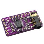
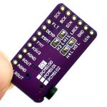
For the testing I now used a PCM5102A on a generic breakout board. Those can be had for pretty cheap. I scored 5pcs for 25€ on amazon.
The PCM5102A is pretty simple. It does not use I²C for configuration, but rather has some Pins that can influence its mode of operation. Rest is determined by the incoming data from I²S.
I went with the following configuration:
FLT -> low
DEMP -> low
XSMT -> high
FMT -> high
This will automatically have the PCM5102A unmuted and waiting for left-aligned data.
Connection to the CSR8765 is made via dunpont connectors, connecting GND, VCC (3.3V), LRCK/SYNC, DIN and BCK. We don't need SCK for this, so that pin can be left open or tied to ground.
https://abload.de/image.php?img=i2s_breakout7ujtt.jpg
https://abload.de/image.php?img=i2s_dac72kax.jpg
There is some configuration to be done inside the ADK Configuration Tool. I am using Version 4.3.15 with the default sink application.
First of all, we need to enable routing of audio to the I²S output channel:
https://abload.de/image.php?img=i2s_audio_config8rkbp.png
Next is the specific I²S configuration:
https://abload.de/image.php?img=i2s_data_configuratiouukyy.png
https://abload.de/image.php?img=i2s_auto_muteicjsw.png
https://abload.de/image.php?img=i2s_initblkj2.png
https://abload.de/image.php?img=i2s_shutdownwvjfv.png
https://abload.de/image.php?img=i2s_volumeqyklw.png
Since the PCM5102A does not have I²C we need to disable all I²C communication, otherwise the CSR8675 gets stuck.
This is done by setting the Number of I²C commands to 0. Also we can configure a ENABLE GPIO which can later be used to automatically soft-mute the DAC via the CSR8675, not using that currently.
Setting that up, the PCM5102A is now appearing in the universal frontend (make sure to have an audio stream running).
https://abload.de/image.php?img=i2s_music_manageragk6j.png
https://abload.de/image.php?img=i2s_crossoverdrjda.png
Dear Tehsiggi, i have a tinysine tsa6175 and i program it via tc025 cable....i don't know if i can cut off with dsp crossover section, the channel separately.
I need a R for low frequency and L for high frequency.
Is possible?
I don' t find a solution
Best regards have a nice day ale
Dear Tehsiggi, i have a tinysine tsa6175 and i program it via tc025 cable....i don't know if i can cut off with dsp crossover section, the channel separately.
I need a R for low frequency and L for high frequency.
Is possible?
I don' t find a solution
Best regards have a nice day ale
Yes it's possible, i just configured this too:
Use ADK 4.3, open adk config tool and set the audio outputs for primary/secondary split:

then open universal frontend, open music manager, connect to the DSP, enter watch mode, open crossover settings and configure the input/output matrix for left to go through primary and right through secondary, then set up the filters as you need the parameters and download the parameters to the PS state through the context UFE menus

BTW i found a hack to get my CSR on a sort-of clean state and working with TWS on 4.3 finally:
- dump PS state on 4.2 fw
- Flashed tinysine firmware with its messed up config state
- module starts but has messed up config state
- open ADK config tool without connecting to SPI, load config values from sink app
- write the sink app default parameters directly without reading first
- CSR is now mostly in default sink app state
- run a dump now
- diff the psr files and port over valid values (USR keys will mostly break the sink code because they have different word lenghts for different ADK versions)
- now the CSR is mostly in the same state as in the previous ADK
I don't understand why there is no way to just generate a .psr for the current sink app because the config definitions contain all the info but w/e this works too i guess...
Many thanks for the top information...
Today i have follow the step that you have showed but after i change the input in primary and master, i click on the write button and the csr restart.
I think the csr is perfectly configured and i think wrong.
The csr not work, the 3 function button not work and the led is in a stable blue status.
I have flashed the original tinysine firmware with blueflash tool for reuse it.
Now it work very well but not with the modify that i need.
Why?
Many thanks
Many thanks for the top information...
Today i have follow the step that you have showed but after i change the input in primary and master, i click on the write button and the csr restart.
I think the csr is perfectly configured and i think wrong.
The csr not work, the 3 function button not work and the led is in a stable blue status.
I have flashed the original tinysine firmware with blueflash tool for reuse it.
Now it work very well but not with the modify that i need.
Why?
Best regards
Hi all
One question : I have a BT headphone that uses a CSR64215 chipset.
I wan to add a special custom EQ profile. Is it possible to extract and modify his FW to add it ? And how ?
Of course, i can dismount and solder something on it, if needed. FYI, this model supports USB audio and mobile app.
Thank you very much !
Hi all
One question : I have a BT headphone that uses a CSR64215 chipset.
I wan to add a special custom EQ profile. Is it possible to extract and modify his FW to add it ? And how ?
Of course, i can dismount and solder something on it, if needed. FYI, this model supports USB audio and mobile app.
Thank you very much !
You would need to find the SPI interface on the board in your headphones so you can connect the programmer. Then just follow the instructions in OP.
- Home
- Source & Line
- Digital Line Level
- CSR8675 programming guide w software and tons of CSR info