Even soic to dip adaptators are a problem - Miro: any soic outputt planned with a separate buf stage as well ?
Vunce did a nice job with his OPA861 separate output stage. Voltage regulator on such a board is a great benefit.
We could make some universal board in the future, that will handle additional tuning

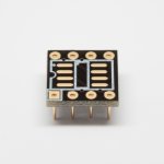
For now use universal soic adapter and solder the legs similiar to this picture and it shortens the connections.
You can always add a capacitor from the top
Attachments
Hi Diyiggy,
Thanks for your SMD capacitor recommendations, I spent a good portion of time yesterday researching parts.
Panasonic ECHU and ECPU series and CDE FCA acrylic series capacitors along with Susumu RS series resistors are all in my next Mouser order.
Don't ask me why, maybe bias, but I find the FCA better at ears while the ECHU are the only one with 5% option of capacitance value precision... The soldering is a mess : do instant soldering with flux and a hot (400°c) solder device : if you work fast the capacitance value don't change... if you rework the solder for whatever reason like the soldering doesn't suit your taste about its gloss etc : value will move... I solder one side at time to make the other one cooling - yes I'm paranoids with those caps
... but they sounds good- Don't try the Rubycons yet...so what about the JLCSounds board and its Lrck for the board ? (vs I2StoPCM) ... with NOS.
I will go with any known simple I2S solution (I don't see a benefit in reclocking for NOS R-2R). You know, everyone prefers something different
For what additional reclocking when almost any xmos based PCB has jitter very low. Also pcm2706/7 is sufficient for R-2R.Thank you .
We agree it is in plus of the pcb 100 nF that are too far for a soic adaptator - we talk stacking cap from above- ?
Edit : what I know is the tda1541A seems to profit also better from a good Lrck that a good Bck from what I readed from very experienced diyers with this chip !
.We agree it is in plus of the pcb 100 nF that are too far for a soic adaptator - we talk stacking cap from above- ?
Edit : what I know is the tda1541A seems to profit also better from a good Lrck that a good Bck from what I readed from very experienced diyers with this chip !
You know that for example, in the 1704 it is not LRCLK any more, but BCLK..
But yes, in the PCM63 it should be LRCLK the trigger signal for the conversion.
Notwithstanding Guido and troops had put a serious effort in synchronizing also BCLK, DATA. They claimed it helped.. Though after I had found many 'entry points' for mods, so it could be different now.
But yes, in the PCM63 it should be LRCLK the trigger signal for the conversion.
Notwithstanding Guido and troops had put a serious effort in synchronizing also BCLK, DATA. They claimed it helped.. Though after I had found many 'entry points' for mods, so it could be different now.
look up the page 7 in datasheet:
"Audio data is supplied to the DATA (pin 1) input. The bit
clock is used to shift data into the PCM1704 and is supplied
to BCLK (pin 2). All DAC serial input data bits are latched
into the serial input register on the rising edge of BCLK. The
serial-to-parallel data transfer to the DAC occurs on the
falling edge of WCLK. "
WCLK = LRCK
BCLK = BCK
DATA = either DR or DL
It "occurs", does it mean it is aligned by? If so, this is what you meant and I did not understand properly what you meant. I understood this:
>>in the 1704 it is not LRCLK any more, but BCLK..
as: LRCLK == BCLK sorry...
Now it makes sense. The output is 2 BCLK delayed and thus "aligned" by.
>>in the 1704 it is not LRCLK any more, but BCLK..
as: LRCLK == BCLK
sorry...Now it makes sense. The output is 2 BCLK delayed and thus "aligned" by.
- Home
- Source & Line
- Digital Line Level
- DAC AD1862: Almost THT, I2S input, NOS, R-2R