I have something like this for SMD work and it helps a lot:
https://www.amazon.ca/Headband-Magn...words=magnifier+glasses&qid=1614701649&sr=8-6
Also, A Rosin Flux pen helps when manually soldering SMD:
https://www.amazon.ca/MG-Chemicals-...=1614701868&sprefix=resin+flux,aps,199&sr=8-6
https://www.amazon.ca/Headband-Magn...words=magnifier+glasses&qid=1614701649&sr=8-6
Also, A Rosin Flux pen helps when manually soldering SMD:
https://www.amazon.ca/MG-Chemicals-...=1614701868&sprefix=resin+flux,aps,199&sr=8-6
.... went till 06 size for the smd caps... Indeed flux is your friend and anyway you need it for a good job at soldering the registers.
Now some caps I like are not below 0805 size, but 04 size with ceramic can be certainly usefull in the digital area when very smal inductance is needed, while a mess for diyers. Certainly not needed for pcm chips, but maybe for modern regs decoupling ???
To answer to sergeliss : modern smd regs are good but like the "quai de Seine", not always needed for a good & safe Week-end trip. Look for instance discrete regs made here and there : Salas or for instance the good serie discrete regs from Audial... they are good, fast, use good caps which them you can adapt the the sounds you like, without wasting the design, etc !
The modern regs though gives you zero layout choice, which is meaning very low size smd for the best , so ceramic Class II (think in piezzo electric noise behavior, you perhaps needs to avoid in the analog domain- tests are the best proof of concept if ok or not in your design).
And sometimes number are not all, for instance there was a hype for a lt3042 ver low noise and rejection smd regs... For a reason I don't understand in real life I always had better results with TS7A which are low noise but noiser than the LT302 ! Go figure ? layout ? Passive parts around ?
More than sometimes, just a measurements don't say it all... If it changes it can be measured surely, but it's maye not the noise level that is in both case very low enough.
Now there is nothing wrong with the regs you 're talking about.
Iggy..
In the last summer I had no better things to do than stay at home amd test regulators.. 😁😄
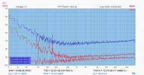
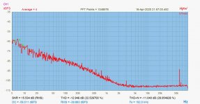
First pic is a noise comparison between a small, 3 terminal shaped TPS7A4700, and an LT3042. The lowest curve is the noise of a 60ohm resistor, that is 1nV/sqrtHz. It's visible that the LT3042 is 6dB higher - 2nV/sqrtHz, as declared.. The TPS is like 10nV/sqrtHz, not that bad at all..
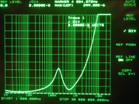
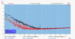
Then, the output imp. curves as taken by my faithful 3577A. Linear vertical scale, not so usual, so don't get surprised about the steeply rising parts. That is normal..
But look, ma, thry're starting above 1MHz..
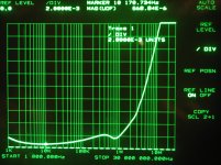
The first is the TPS curve, below 100kHz goes deeper than the next curve, the LT3042. But look how less resonant is this second one, and extends above 1MHz.
The value is like measured 2/3mohm for TPS, cca 5mohm for LT3042.
And sometimes number are not all, for instance there was a hype for a lt3042 ver low noise and rejection smd regs... For a reason I don't understand in real life I always had better results with TS7A which are low noise but noiser than the LT302 ! Go figure ? layout ? Passive parts around ?
In the last summer I had no better things to do than stay at home amd test regulators.. 😁😄
First pic is a noise comparison between a small, 3 terminal shaped TPS7A4700, and an LT3042. The lowest curve is the noise of a 60ohm resistor, that is 1nV/sqrtHz. It's visible that the LT3042 is 6dB higher - 2nV/sqrtHz, as declared.. The TPS is like 10nV/sqrtHz, not that bad at all..
Then, the output imp. curves as taken by my faithful 3577A. Linear vertical scale, not so usual, so don't get surprised about the steeply rising parts. That is normal..
But look, ma, thry're starting above 1MHz..
The first is the TPS curve, below 100kHz goes deeper than the next curve, the LT3042. But look how less resonant is this second one, and extends above 1MHz.
The value is like measured 2/3mohm for TPS, cca 5mohm for LT3042.
Attachments
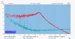
For comparison, here it is an LM317 standard config, already with adj. Bypass; as confronted to an LT3042;
An ADUM7150 (another good regulator..)
And finally some test on a LT3042, with different (increasing) noise filter caps - lowest noise curve is a cca 20uF MLCC... (bleacch)
An ADUM7150 (another good regulator..)
And finally some test on a LT3042, with different (increasing) noise filter caps - lowest noise curve is a cca 20uF MLCC... (bleacch)
Attachments
... I loved SMD components but gradually I fell back in love with THT 
These audio devices will almost always contain some THT components (PSU filtration, DAC chip, connectors). Some things can't be done effectively in THT, then I'll use SMD, but I'm trying to eliminate SMD. So as a result it's a mix of components anyway
THT advantages from my view:
- soldering will be more plaything for fingers and less effort for eyes
- the choice of components is wider because even SMD components can often fit between some THT holes
- many THT components are sound proved
- vibration does not affect the sound
- device looks more interesting to look at, definitely more DIY look
- device can be thermally and mechanically stressed with lower lifespan degradation thanks to THT legs
- solder joints are bigger, stronger
THT disadvantages:
- device is bigger (Here's the question, will it be portable or will it have its place?)
- build price can be higher
- high-speed devices may encounter a problem
SMD advantages:
- digital high-speed
- price
- size
@Joseph K
Very valuable testing, thank you for it
@diyiggy
We look forward to your comparisons, thank you
@Vunce
Don't worry Vunce, there will come a lot of SMD soldering on my future PCBs, you know what I mean
@Sergelisses
>>Why this choice LT1963 and LT3015 ?
This PDF led me to those components A comparative overview of power supply regulator designs with listening tests - PDF Free Download
and also because of the still unsurpassed popularity of THT
Last edited:
@Vunce
Don't worry Vunce, there will come a lot of SMD soldering on my future PCBs, you know what I mean
Hahaha!! Can’t wait Miro.
Check out the lined up 0603’s, like a machine!
I agree with you Miro and Joseph K, a nice mix of parts style is good thing. The benefits of space saving and a broader parts selection. Win Win for everyone
Attachments
Last edited:
Miro,
I do agree with You about THT parts. I do value them as well, or rather, I learned to value them with time, like You are saying. Obviously for speed and clean signals SMD is best. But ceramics are microphonic, and rigidly attached to a resonant plate ( pcb..). Also much greater thermal excursions in (small) smd parts. And though some families fare well , yes THT parts are the real tested, known behaviour elements to build upon..
So a carefully mixed design is my ideal, too..
Ciao, George
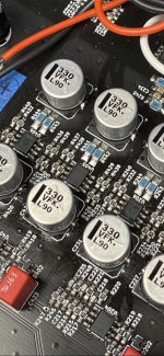
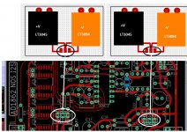
Finally, You don't need to be forced to use only MLCC capacitors for an LT3042 reg..
Here they are PMLCAP & PPS films, in the critical positions.. (that'a dual, +_regulator board)
Hello Joseph
Do you have created these boards
I like when inputs and outputs are on the opposite side
Serge

Hello
An idea , not original to limit the length of cables !!!
I have not the tools and the experience to design and try this "project"
Serge
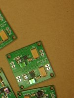
This is exactly my plan.
And the third revision of the PCBs arrived yesterday.

This is exactly my plan.
And the third revision of the PCBs arrived yesterday.
View attachment 928170
Very good
Do you have an idea about the PCB price
Thanks
Serge

Very good
Do you have an idea about the PCB price
Thanks
Serge
The price is something like $5 for 5 pcbs plus $14 shipping from CN.
Takes about 12 days to get to the US.
If you guys like it, I can share the kicad project so someone with better engineering skills/experience can verify the PCB layout and improve it, before ordering multiples.
Finally, You don't need to be forced to use only MLCC capacitors for an LT3042 reg..
Here they are PMLCAP & PPS films, in the critical positions.. (that'a dual, +_regulator board)
But if you buy it on a pcb already populated with less than 0805 pads size
I have an heavy incompatibility taste with MLCC from a long time, and if the Class I have not piezzo behavior on the pcb, when the value are near 0.1 uF and more I prefer to swap them with pmlcap or PPS... with a carefull and fast soldering not to drift their capacitance value...
Thanks for all the measurments, so your conclusion is my ears are not so bad ?
Last edited:
Hi Miro,
Built this DAC some time back and it is singing beautifully !!.
I was curious on the R8 and R9 Resistors, i am aware that the resistor value here corresponds to Gain, currently 1.8K is used.
Is there any sweetspot for the gain? or the gain here does not have any influence on the quality.
Opamp used is LM6171. If there is no degradation because of this, i would try a bit higher gain may be a 2.7k.
Thanks
Harsha
The lower the value the better, but the less gain. All is about about the next load.
95% you don't need the text book 2V but if you have a passive pre.
You can perfectly live with this value and even less. Gives you the advantage to pump the volume pot up that often works better at 12h00 position than 8 hours attenuation.
95% you don't need the text book 2V but if you have a passive pre.
You can perfectly live with this value and even less. Gives you the advantage to pump the volume pot up that often works better at 12h00 position than 8 hours attenuation.
But if you buy it on a pcb already populated with less than 0805 pads size
For this reason we have created our own, 4 layer pcb..
About MLCC.. I have recently done some 'screening' of different capacitors., on my HP4276 LCZ meter..
Will try to assemble the results in a little presentable format.
But MLCC capacitors are about everything, but capacitors..
I knew about their temperature; vibration dependency; the very high voltage coefficient;
But from these recent scans I learned about the C/frequency non-linearity..
Like a 40uF Zu type piece of rock had lost 35% of it's value, while sweeping from 50Hz to 1KHz..
This was new to me: so You place a "capacitor" on your drain-output LDO stage: the output voltage will change in function of bypass capacity; but that C is changing, in function of load current frequency..
Obviuosly, film (and acrylic or PMLCAP) capacitors are just boring, behave like capacitors.. At each frequency.
- Home
- Source & Line
- Digital Line Level
- DAC AD1862: Almost THT, I2S input, NOS, R-2R