Designing a good TH is not trivial - and sometimes it is best to use a well-accepted design as a reference. Take the TH-18 (http://www.diyaudio.com/forums/subwoofers/190635-th-18-flat-35hz-xoc1s-design.html), which has had many successful builds and I believe is one of the better designs out there for a larger TH given how much iteration, refinement, and work went into it. If you want to back up your rather grand claim of:
See if you can make a straight walled TL with performance that will beat the TH-18 for the same volume and power, and maintain a flat bandwidth from 37Hz to 120Hz with 99.5dB (+/- 3dB) at 2.83v/1m.
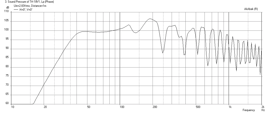
Here is the performance of the TH-18 with an 18 Sound LW2400 driver at 2.83v:
Here is the script for this speaker from the above thread:
Horns are not efficient att producing bass!!!
See if you can make a straight walled TL with performance that will beat the TH-18 for the same volume and power, and maintain a flat bandwidth from 37Hz to 120Hz with 99.5dB (+/- 3dB) at 2.83v/1m.
Here is the performance of the TH-18 with an 18 Sound LW2400 driver at 2.83v:
Here is the script for this speaker from the above thread:
Code:
|Rev5 - Model based on how geitmans built the spud script and now accounting for Vtc

|TH-18 Flat to 35hz! (Xoc1's design) on DiyAudio.com Collaborative effort

|I have not taken into account the bracing as it makes my head spin adding so many sections of script (I am working on it though)

|TundraLTD Enjoy!!


|================================================= ================================================== ================================================== ============

|Network node numbers for this tapped horn system:

| 0-Voltage-1
| |
| -Chamber-5-Driver-------------------------------------------------------------------------------------------------------------
| | |
|8-Duct-9-Duct-10-Duct-11-Duct-12-Duct-13-Duct-14-Duct-15-Duct-16-Duct-17-Duct-18-Duct-19-Duct-20-Duct-21-Duct-22-Duct-23-Duct-24-Duct-25-Duct-26-Duct-27-Radiator

|================================================= ================================================== ================================================== ============

Def_Const | Data for Vtc Chamber
{
Vtc = 7873.00e-6; |Throat chamber volume (cubic m)
Atc = 1210.00e-4; |Throat chamber cross-sectional area (sq m)

Sd = 1210.00e-4; |Diaphragm area (sq m)

Ltc = Vtc / Atc;
}

Def_Driver 'Driver'

|READ THIS
|Simply remove the block for the driver you wish to Sim
| <-block (in front of Sd) REMEMBER to only have one drive unblocked at a time

|18Sound 18LW2400-8
 Sd=1225.00cm2 Bl=25.77Tm Cms=1.07E-04m/N Rms=5.90Ns/m fs=35.0003Hz Le=1.35mH Re=5.00ohm ExpoLe=1

|B&C 18SW115-8
| Sd=1210.00cm2 Bl=28.31Tm Cms=1.21E-04m/N Rms=10.10Ns/m fs=30.9998Hz Le=1.70mH Re=5.10ohm ExpoLe=1

|B&C 18TBW100-8
| Sd=1210.00cm2 Bl=30.07Tm Cms=8.38E-05m/N Rms=6.78Ns/m fs=35.0003Hz Le=2.45mH Re=6.50ohm ExpoLe=1

|Precision Devices PD1850-8
| Sd=1150.00cm2 Bl=31.41Tm Cms=1.32E-04m/N Rms=6.65Ns/m fs=29.9999Hz Le=1.00mH Re=5.40ohm ExpoLe=1

|BMS 18N850v2-8
| Sd=1213.00cm2 Bl=25.11Tm Cms=1.18E-04m/N Rms=6.10Ns/m fs=29.7001Hz Le=0.89mH Re=5.00ohm ExpoLe=1

|Void Acoustics V18-1000-8
| Sd=1230.00cm2 Bl=34.96Tm Cms=9.35E-05m/N Rms=6.46Ns/m fs=34.5311Hz Le=2.20mH Re=5.50ohm ExpoLe=1

|18Sound 18NLW9600-8
| Sd=1134.00cm2 Bl=30.55Tm Cms=8.13E-05m/N Rms=6.62Ns/m fs=33.9997Hz Le=2.11mH Re=4.70ohm ExpoLe=1


System 'System 1'


Filter 'HighPass' |Highpass filter - 12dB Butterworth (change 'fo=***' and refresh for changes)
fo=30Hz vo=1
{b2=1;
a2=1; a1=1.414214; a0=1; }

OFF
Filter 'LowPass' |Lowpass filter - 48dB Butterworth (change 'fo=***' and refresh for changes)
fo=100Hz vo=1
{b0=1;
a8=1; a7=5.125831; a6=13.137071; a5=21.846151; a4=25.688356; a3=21.846151; a2=13.137071; a1=5.125831; a0=1; }

Driver Def='Driver'
Node=1=0=25=5

Duct 'Throat chamber' Node=5=9 SD={Atc} Len={Ltc} visc=1
Duct 'D1' Node=8=9 HD=53.5cm WD=5cm Len=21.92cm visc=50
Duct 'D2' Node=9=10 HD=53.5cm WD=8.6cm Len=19.23cm visc=50
Duct 'D3' Node=10=11 HD=53.5cm WD=11.8cm Len=6.75cm visc=50
Duct 'D4' Node=11=12 HD=53.5cm WD=10.4cm Len=24.92cm visc=1
Duct 'D5' Node=12=13 HD=53.5cm WD=12.1cm Len=10.6cm visc=1
Duct 'D6' Node=13=14 HD=53.5cm WD=12.9cm Len=11.5cm visc=1
Duct 'D7' Node=14=15 HD=53.5cm WD=13.8cm Len=15.17cm visc=1
Duct 'D8' Node=15=16 HD=53.5cm WD=14.9cm Len=9.35cm visc=1
Duct 'D9' Node=16=17 HD=53.5cm WD=15.5cm Len=9.54cm visc=1
Duct 'D10' Node=17=18 HD=53.5cm WD=16.2cm Len=8.6cm visc=1
Duct 'D11' Node=18=19 HD=53.5cm WD=16.8cm Len=11.72cm visc=1
Duct 'D12' Node=19=20 HD=53.5cm WD=17.6cm Len=15.21cm visc=1
Duct 'D13' Node=20=21 HD=53.5cm WD=18.7cm Len=16.42cm visc=1
Duct 'D14' Node=21=22 HD=53.5cm WD=19.9cm Len=49.74cm visc=1
Duct 'D15' Node=22=23 HD=53.5cm WD=23.4cm Len=10.26cm visc=1
Duct 'D16' Node=23=24 HD=53.5cm WD=26.9cm Len=11.11cm visc=1
Duct 'D17' Node=24=25 HD=53.5cm WD=29.6cm Len=28.49cm visc=20
Duct 'D18' Node=25=26 HD=53.5cm WD=40.9cm Len=28.49cm visc=1
Duct 'D19' Node=26=27 HD=53.5cm WD=50.8cm Len=19.93cm visc=1
Radiator 'R1' Def='D19' Node=27
Attachments

Last edited:


I found this data in the thread you linked to, so i simmed it with another driver.
I hope this is right. I used B&C 18NW100 instead. I need some Bl if i am going to make it work.
The whole basis for this thread is still this:
If you try to get a high power density from powerful (low Qes, High Bl, high mms) drivers like B&C 12NW100 in a tapped horn you get a very high compression or a very deep depression in the middle of the passband
Cheers,
Johannes
you want to back up your rather grand claim of:
Quote:
Horns are not efficient at producing bass!!!
Of course i want to, but i was not totally serious when i wrote that line.
Sorry about omitted smiley.
I have been building bashorns and tapped horns for many years now.. I prefere basshorns above every other kind of box.
Cheers,
Johannes
I prefere basshorns above every other kind of box.
I like bass horns too and currently use one for a sub. Getting back to the thread topic, I still think it is a bass horn and not a tapped horn. I wonder what the effect of having the output of 4 bass horns coming out together at one point does? I hear that this can extend bass extension by making the effective mouth size larger which supports lower wavelengths. Not sure if this can be captured in a sim with either Akabak or HR.
Oliver,
Hornresp seems to ignore the effect of a segment going out to a larger flat boundary, while I have measured a 3 dB increase in LF response doubling frontal area.
Just another one of those things that keeps me making sawdust rather than spending too much time simulating.
Art
Hornresp simulates waveguides.
You are trying to simulate a boundary as a large round waveguide with almost infinitely small length (almost flat). There's no wonder it doesn't work.
There are plenty of tools that will simulate a boundary. I'm not sure why people want to try to force the program that absolutely can't do it to try to do it and get surprised that it didn't work.


Not really what you asked for, but here is a smaller box with a total Sd of 1062 cm2 instead of 1225 cm2 (86,69%), and a xmax of 10 mm instead of 9,5 (105,26%) playing almost 10 dB louder at 80 - 100 Hz. I would say the 18SOUND 18LW2400 is a more powerful driver then 2 B&C 12NW100, except for the thermal power rating of the voicecoil.
The THBD is 4,46 liter smaller. Probably compensated for by the volume the drivers occupy.
Even though the 18Sound has more radiating surface and almost the same xmax (a total larger ability to move air) the THDB will play substantially louder in the very important frequencys around 70 - 120 Hz.
I have not worked a lot at this simulation. It took me about 15 minutes.
I have no idea if i could get it better than this, but i can not see why.
I know this is not a fair comparison, but i have seen that this kind of strange box does not work well with to weak drivers. The Ipal18 is the only 18 inch driver that is effective. It is most powerdense with really strong and efficient drivers like the B&C12NW100, IPAL18, Faital Pro 10HP1020 etc...
I will try more later on.
This was just a fast rough draft..
Cheers,
Johannes
Hi all!
I have been trying to figure out the Danley BC line of subbs.
This is what i think is going on:
If you try to get a high power density from powerful (low Qes, High Bl, high mms) drivers like B&C 12NW100 in a tapped horn you get a very high compression or a very deep depression in the middle of the passband, like i show below:
http://oi59.tinypic.com/14mzaxv.jpg
I have two more posts to make, please wait until i have posted them before you reply.
Cheers,
Johannes
I'm not sure what you consider "high power density" but I made a couple of very small changes to your sim in post #3 to make it a more conventional flare shape and I got the same sensitivity, more bandwidth and no deep depression. Same size too. (Small changes to S3, S5 and L45 give this response.)
An externally hosted image should be here but it was not working when we last tested it.
I was also able to get almost exactly the same response as the design in post #3 by using different flare shapes, a bowtie shape like Kravchenko used a few years ago gives the same response.
So I'm not sure what's new here, a more regular tapped horn works just as well (and has more bandwidth)and the method to get the two octave wonky response with the extra strong middle resonance as shown is achievable by different flare shapes.
Last edited:
A large round waveguide with almost infinitely small length is a 180 degree waveguide.Hornresp simulates waveguides.
You are trying to simulate a boundary as a large round waveguide with almost infinitely small length (almost flat).
There are plenty of tools that will simulate a boundary.
What tools will accurately simulate a boundary of 60" x 60"?
I'm not sure what you consider "high power density" but I made a couple of very small changes to your sim in post #3 to make it a more conventional flare shape and I got the same sensitivity, more bandwidth and no deep depression.
18 inch drivers are not powerful enough to take any benefit from this kind of th-hybrid.
Test the same thing with a B&C 12NW100..
Cheers,
Johannes
A large round waveguide with almost infinitely small length is a 180 degree waveguide.
What tools will accurately simulate a boundary of 60" x 60"?
I know a large round waveguide with infinitely small length is a 180 degree boundary in theory but clearly Hornresp doesn't simulate it properly, and even if it did it would be simulating a round waveguide without diffraction so it still wouldn't be doing what you want.
Akabak and MJK's worksheets will do it (but MJK's software won't sim exponential horns or tapped horns).
Also there are a variety of tools that use .frd and .zma files that can add a baffle and diffraction effects to a response graph. Bagby's Diffraction and Boundary simulator is one to look at, and Response Modeler will combine the Hornresp response with the diffraction response.
18 inch drivers are not powerful enough to take any benefit from this kind of th-hybrid.
Test the same thing with a B&C 12NW100..
Cheers,
Johannes
If this method is not useful for an 18 inch driver why did you use that driver in post 3 to describe this process?
Tell me which post contains the sim that you would like me to look at with the 12NW100 and I'll take a look.
But what you are showing is a stepped horn with two steps. We see this all the time, but without the steps, the basic shape is shown below. This shape is very common and it does the same thing, it boosts the frequencies at the top of the passband.
An externally hosted image should be here but it was not working when we last tested it.


If you would like to take a look at this sim, i would be grateful.
If this method is not useful for an 18 inch driver why did you use that driver in post 3 to describe this process?
I have learned a lot during this thread. I started out with 12NW100 and faital Pro 10HP1020, and i thought it would work just as good with powerful 18 inch drivers. Now i have seen that this is not the case. IPAL18 is the only 18 inch driver strong enough.
It looks to me to be the same thing over again, like when Tom Danley developed the tapped horn to suit and take advantage of more powerful drives of the day. This happens once again with 12 inch drivers with a Bl of 28 or more. A guess a 18 inch driver with a Bl of 45 to 50 and a Mms of 300 grams should work well.
Cheers,
Johannes
I have to clarify.
This TH-hybrid works with almost any driver, but is more suited to very strong and powerful drivers. It does not seem to provide any real benefits in dB/dm3 (power density) with "normal" medium Bl, medium Qts and Mms drivers like the B&C 15TBX100 or 18TBX100.
The 12NW100 seems to be on the verge. I guess a 12 inch driver based on the IPAL18 motor would be a really good candidate.
I think this is a really exciting development. I believe drivers for basshorns will be more and more similar to compression drivers soon. A steel cone with a huge neodymium magnet structure, lots and lots of xmax and Bl, all in a hugh package where you don´t even see the cone. Probably two magnets and two voice-coils, sort of like two drivers in isobaric..
Cheers,
Johannes
http://www.powersoft-audio.com/en/d...-9060-a-novel-moving-magnet-linear-motor/file
It is a good start...
It is a good start...
View attachment 445535
View attachment 445536
If you would like to take a look at this sim, i would be grateful.
No problem.
This is just a game of playing with the flare shape to place the impedance peaks where you want them. I've been doing this for awhile so this didn't take more than 10 minutes.
First goal - keep my examples roughly the same size as yours (110.527 liters).
Goal 2 - keep S2 and S4 on auto (no more than 2 different flare rates).
Goal 3 - try to match your response curve, especially the low knee (can't beat it without using more space, so the goal was just to recreate what you had with different shapes of flare)
Comparison 1
Your design compared to a simple tapped horn. I couldn't get the peaks to match yours in position (frequency) in the size I was allowed so yours has a bit of advantage from 60 - 200 hz but the simple tapped horn has the advantage everywhere else, and it has more bandwidth too, with slightly less excursion. If I was allowed more degrees of freedom (S2 and S4 manual and or a few extra liters) I could match your response much more closely. Same power applied to each, same sensitivity, same size (mine is 1.5 liters larger).
An externally hosted image should be here but it was not working when we last tested it.
Comparison 2
Like I said, a bowtie shape will get your the same response so the method of achieving it isn't very important. This is your design compared to a bowtie shape, same power applied, exactly the same sensitivity, almost the same size (bowtie is 11 liters larger than yours). S3 is a bit small but this is just an example to show how you can get just about whatever response curve shape you want, and you can do it with different flare shapes too.
An externally hosted image should be here but it was not working when we last tested it.
I've said this a few times but it bears repeating. There is no magic design or alignment that produces more resonant output than others. For a given size they are all pretty similar.
You have a handful of impedance peaks to work with. The size of the enclosure (and boundary loading) determines max potential resonant output. The flare shape determines the spacing between the impedance peaks and how strong each of them individually will be.
If you space the impedance peaks close together you can get response peaks, or a sensitivity boost over a small passband (like a peaky 6th order bandpass). If the space the impedance peaks evenly you can get 3 octaves of resonant output but without the peaky response.
You might be surprised how far you can push this idea. I've simulated, built and measured a massively undersized front loaded horn (100 liters for a 6.5 inch driver, 30 hz low knee), it had almost ruler flat response (no rising response and peaks no bigger than a ripple) and high(ish) sensitivity for two octaves. I could have made it much smaller and maintained the flat response but without the sensitivity.
I forgot to include a schematic of the original design.
An externally hosted image should be here but it was not working when we last tested it.
After a bit of refinement I recreated your response curve almost identically (with the exception of a greatly increased bandwidth) with a simple tapped horn. (See what I mean about getting the same response with different flare shapes?)
The simple tapped horn is 10 liters larger, same power applied to each.
The simple tapped horn is 10 liters larger, same power applied to each.
An externally hosted image should be here but it was not working when we last tested it.
One final example, a front loaded horn, same driver, same size enclosure compared to your design. Same power applied. The flh has much less excursion so given enough power it could go considerably louder within xmax. Compression ratio is a bit high, but again this is an example to show how the response curve shape of the original design is easily duplicated by entirely different designs.
I could probably get a better match if I spent a bit more time but this should show that regardless of the alignment - ported, tl, tapped horn, back loaded horn, front loaded horn - the resonant output is determined by the size of the enclosure.
Also, regardless of the alignment, adjusting the flare shape will give you just about any response curve shape you want.
I don't find the response curve shape of the original design to be very attractive but it doesn't really matter because anyone can have any curve shape they like with a little adjustment.
An externally hosted image should be here but it was not working when we last tested it.


Thanks Just a Guy for taking the time and effort for some very interesting simulations and comparisons.
I let my THBP catch up on size to your last TH.
My basis for this thread was this:
"If you try to get a high power density from powerful (low Qes, High Bl, high mms) drivers like B&C 12NW100 in a tapped horn you get a very high compression or a very deep depression in the middle of the passband, like i show below"
And compression is something i take very serious in these kind of high power applications.
200 cm2 is the absolute highest compression i can accept in my design, but i really don´t like anything below 250 cm2 (S2). I had a Beyma 12LX60 in a tapped horn with 250 cm2 S2, and after about 5 seconds of some bass-heavy music driven by my bridged QSC RMX 1450 (not clipping) (800 watts into 8 ohm) the cone cracked and buckled. The B&C 12NW100 is a more powerful and more robust driver, but i still don´t like to much compression. I seems fine in Hornresp, but when driven hard, failure is just a matter of time or a dropped microphone away.
The deep depression above the intended passband is not a fault. It is an advantage. It will lower distortion substantially...
Again, Thanks for some very interesting simulations!
Cheers,
Johannes
- Home
- Loudspeakers
- Subwoofers
- Danley BC-subs reverse engineered