Look back through my posts on input cap distortion testing on the wolverine, you maybe might not want to use that cap.I use these cap ( Clarity Cap CSA) just because….
I had them in stock
But yes it’s a very compact and nice cap
And price (in Europe) is not high (less than 10 euros)
Input impédance is 22 k( easier for tube preamp in case of…)
Very nice work duniel,why i can't see the controller board?Starting to get close....
I have had a listen in stereo now, very happy...
View attachment 1166779 View attachment 1166780

Starting to get close....
I have had a listen in stereo now, very happy...
View attachment 1166779 View attachment 1166780
Very very nice amplifierStarting to get close....
I have had a listen in stereo now, very happy...
View attachment 1166779 View attachment 1166780
Congratulations !
Toroidy transformers are very impressive
Just a question:
your rectifiers have no heatsinks. Not necessary even with very high power use ? (say public address for example)
I used to put heatsinks on all the rectifiers of my Class A amplifiers but here, of course, it's a class AB amp
Thanks for the kind wordsOh my!!!!!. This MUST be the King of the Wolverine herd...🤴🤴🤴🤴
Rectifiers can be installed on the bottom plate, no need for heatsink, like I did with my boards.Hi Thimios, controller board is under the second level so it is close to the speaker protection 😀
Hi Bouli, very observant
Attachments
OK !Look back through my posts on input cap distortion testing on the wolverine, you maybe might not want to use that cap.
Very good and informative job
Il will be very easy to change the caps for the Vishay (thanks to the removable IPS boards)
@Vunce and @fireanimal....I've ordered 4 pairs of the mosfet rectifiers with Prasi which you solder on his PSU boards with some 90 degree sip headers. Which mosfet and or LT4320 is preferred for this setup?
thx in advance
reg
willem
thx in advance
reg
willem
yep... you're right...very good infowhole thread
My very first diy and thanks to superb build guide, i managed to put it together and first measurements show that everything works as expected. Thanx again to the team and to the Community! Still need some tidyup and lot to do before i can enjoy my favorate music from wolverine. Awesome!
Attachments
The internal organization of an amplifier is always the subject of endless debate.
For the Wolverine, as seen throughout these pages, the recommended method is to place the left channel amplifier board with the transistors facing down and the right channel amplifier board with the power transistors facing up.
I'm not sure the thermal conditions for the power transistors are exactly the same for both channels but I haven't done any studies on this... So...
This leads us to have the power and output connectors of the boards very close to the front of the amplifier. If we use EF3-4 cards and therefore a deep chassis, stacked toroids close to the front side, we will have quite long cable lengths. This is probably not a problem for the output cables but for the power cables (capacitor bank to amplifier boards) I must admit that it is a (little) source of concern. Between 45/55 cm of cable. Of course we have also capacitors on the amplification cards and this probably puts an end to a possible "problem".
I tried a slightly different method for the wiring of my amplifier without any guarantee that it is better but as it works perfectly, the amp is "dead silent", I take the liberty to present it to you.
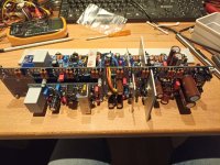
The assembly of the left channel remains identical with the power transistors facing down
For the right channel it's also the case with also the power transistors facing down
As the boards are not mirrored, this leads us to have the left channel power connectors near the front of the amplifier and the right channel power connectors near the back of the amplifier. For the output connectors it's exactly the same thing.
We can try to take advantage of this asymmetry to position the power supply modules and minimize the length of the cables.
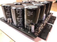
By using low profile toroidal transformers (600VA) and despite the limited internal height of my chassis, it is possible to superimpose the power rectifiers and capacitor bank on top of the toroids with spacers that will be fixed on the bottom plate. The transformers are very oversized and do not heat up. The aluminium sheet is used as a screen and also as a "heatsink" for the two rectifiers which are bolted on with thermal paste.
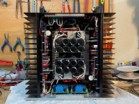
This gives us a "power module" for the left channel very close to the front panel and a "power module" for the right channel very close to the back panel
The cable lengths are therefore minimal
We can also be sure that the thermal conditions for the power transistors of both channels are perfectly identical
For the Wolverine, as seen throughout these pages, the recommended method is to place the left channel amplifier board with the transistors facing down and the right channel amplifier board with the power transistors facing up.
I'm not sure the thermal conditions for the power transistors are exactly the same for both channels but I haven't done any studies on this... So...
This leads us to have the power and output connectors of the boards very close to the front of the amplifier. If we use EF3-4 cards and therefore a deep chassis, stacked toroids close to the front side, we will have quite long cable lengths. This is probably not a problem for the output cables but for the power cables (capacitor bank to amplifier boards) I must admit that it is a (little) source of concern. Between 45/55 cm of cable. Of course we have also capacitors on the amplification cards and this probably puts an end to a possible "problem".
I tried a slightly different method for the wiring of my amplifier without any guarantee that it is better but as it works perfectly, the amp is "dead silent", I take the liberty to present it to you.
The assembly of the left channel remains identical with the power transistors facing down
For the right channel it's also the case with also the power transistors facing down
As the boards are not mirrored, this leads us to have the left channel power connectors near the front of the amplifier and the right channel power connectors near the back of the amplifier. For the output connectors it's exactly the same thing.
We can try to take advantage of this asymmetry to position the power supply modules and minimize the length of the cables.
By using low profile toroidal transformers (600VA) and despite the limited internal height of my chassis, it is possible to superimpose the power rectifiers and capacitor bank on top of the toroids with spacers that will be fixed on the bottom plate. The transformers are very oversized and do not heat up. The aluminium sheet is used as a screen and also as a "heatsink" for the two rectifiers which are bolted on with thermal paste.
This gives us a "power module" for the left channel very close to the front panel and a "power module" for the right channel very close to the back panel
The cable lengths are therefore minimal
We can also be sure that the thermal conditions for the power transistors of both channels are perfectly identical
Attachments
Last edited:
Hi Dan
Thanks
The amplifier is connected to my workshop loudspeakers and I hear no noise (even if I put my ear very close of the tweeter)
I will let the amplifier "burning" like that a few hours or some days
After that and if it's OK I will connect it to my system
I have also a new set of measures for the amplifier (previous screenshots of waves were taken with lab power supply 32V)
I will also change the input capacitors as discussed with @fireanimal
Last edited:
That is good to hear, I am in a similar situation I have mine running in the workshop at the moment. No hum/hiss on idle.
Great to see another build coming together.
I hope you like the sound & performance.
I have been really enjoying listening to mine.
- Dan
Great to see another build coming together.
I hope you like the sound & performance.
I have been really enjoying listening to mine.
- Dan
Groundlift / groundloop breakers,
Helo Gents,...i'm trying to understand the groundlift scheme. The main idea is clear to me however I see various implementations. I'm using the powersupply example which comnes with the wolverine documentation but I also see different ones where the ground coming from the PSU/amp is connected to 1 AC side of a fullwave bridge and the other to the chassis ground with + and - shorted whereas the powersupply example is connected different.

reg
willem
Helo Gents,...i'm trying to understand the groundlift scheme. The main idea is clear to me however I see various implementations. I'm using the powersupply example which comnes with the wolverine documentation but I also see different ones where the ground coming from the PSU/amp is connected to 1 AC side of a fullwave bridge and the other to the chassis ground with + and - shorted whereas the powersupply example is connected different.
reg
willem
That is not for ground lift, it's for safety. You can use a bridge, or a thermistor always connected from power supply ground to chassis.
The board I sent to you has provision for a thermistor connected from PS ground to chassis.
Wouldn't worry about too much, amp will work without it also.
The board I sent to you has provision for a thermistor connected from PS ground to chassis.
Wouldn't worry about too much, amp will work without it also.
- Home
- Amplifiers
- Solid State
- DIY Class A/B Amp The "Wolverine" build thread