Ok thanks!For this one, I would not go beyond total 70V plus to minus, whether bipolar or single-ended. I recall Papa saying the JFETs can withstand up to 70V, but not sure that will ever be used. My own supply wa +-27V and I wouldn't go beyond +-35V.
You can just change the zeners to get the the required voltage, if the raw supply is capable of > than the regulated voltage minus the Vgs, plus a few volts for staying within regulation.
Conclusion, it doesn't look encouraging for eliminating the coupling capacitors C1, C2 and C3.
I think there is a possibility to eliminate C1 and C2 from the circuit (retaining C3) provided that:
- You are willing to tweak R7 to get the offset into a reasonable range.
- You can live with the thermal drift.
See post #567 in this thread.
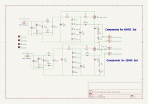
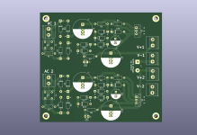
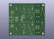
It looks like there is interest in my power supply board so here are the board top and bottom views, and schematic. Note that some component values may need to be tweaked in order to get the exact voltages shown on the schematic. So the indicated output voltages are approximate. This is diy, so tweaking should be expected. ")
The board is 100mm x 100mm. The board can be used for two single voltage supplies or for one bipolar (V+ and V-) supply.
I ordered my boards from JLCPCB.
The output voltage is set by the sum of the zener diode voltages (D9 to D13 and D14 to D18) minus Vgs of the mosfet. R3 and R4 drop the input VDC to the voltage set by the zener strings. Choose a resistance based on about 5mA to 10mA current through the resistor to create the required voltage drop. The same current continues onward through the zener string and then to ground. Use this current to calculate the resistor and zener diode power dissipation.
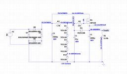
For those who are not familiar with this type of voltage regulation, I have included a screen shot of a LTSpice simulation. Included are voltages and currents at various location to show what happens in the circuit. Note that this is a simulation and the numbers in real life may vary from those in the simulation. I also chose components that were readily available in LTSpice. However the simulation does show how the regulator works electrically.
For those that would like copies of the Gerber files, please message me. I do not want to clutter this thread with requests.
The board is 100mm x 100mm. The board can be used for two single voltage supplies or for one bipolar (V+ and V-) supply.
I ordered my boards from JLCPCB.
The output voltage is set by the sum of the zener diode voltages (D9 to D13 and D14 to D18) minus Vgs of the mosfet. R3 and R4 drop the input VDC to the voltage set by the zener strings. Choose a resistance based on about 5mA to 10mA current through the resistor to create the required voltage drop. The same current continues onward through the zener string and then to ground. Use this current to calculate the resistor and zener diode power dissipation.
For those who are not familiar with this type of voltage regulation, I have included a screen shot of a LTSpice simulation. Included are voltages and currents at various location to show what happens in the circuit. Note that this is a simulation and the numbers in real life may vary from those in the simulation. I also chose components that were readily available in LTSpice. However the simulation does show how the regulator works electrically.
For those that would like copies of the Gerber files, please message me. I do not want to clutter this thread with requests.
Attachments
Yes, I saw that.See post #567 in this thread.
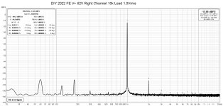
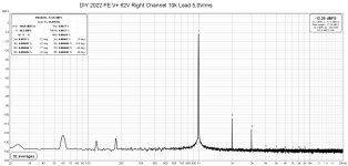
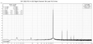
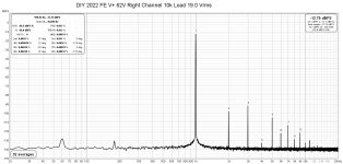
I did some distortion measurements today. Just to recap, the DIY 2022 FE supply voltage was +62V, and I loaded the output with a 10k resistor for these measurements. The highest output that I measured was 19.0 Vrms, and that was limited by my 1kHz oscillator's maximum output.
The right channel was measured over a range of output voltages. I only made one measurement of the left channel, just to confirm that it was similar to the right channel.
The noise is 94.5dB below the 1Vrms signal so I am happy with the power supply.
The right channel was measured over a range of output voltages. I only made one measurement of the left channel, just to confirm that it was similar to the right channel.
The noise is 94.5dB below the 1Vrms signal so I am happy with the power supply.
Attachments
-
 DIY 2022 FE V+ 62V Right Channel 10k Load 1.0Vrms.jpg241.9 KB · Views: 429
 -
 DIY 2022 FE V+ 62V Right Channel 10k Load 3.0Vrms.jpg240 KB · Views: 415
 -
 DIY 2022 FE V+ 62V Right Channel 10k Load 5.0Vrms.jpg240 KB · Views: 357
 -
 DIY 2022 FE V+ 62V Right Channel 10k Load 10.0Vrms.jpg240.3 KB · Views: 341
 -
 DIY 2022 FE V+ 62V Right Channel 10k Load 15.0Vrms.jpg240.4 KB · Views: 331
 -
 DIY 2022 FE V+ 62V Right Channel 10k Load 19.0Vrms.jpg240.3 KB · Views: 337
 -
 DIY 2022 FE V+ 62V Left Channel 10k Load 19.0Vrms.jpg240.1 KB · Views: 424

Nelson in his article said:
Conclusion
And there we have it. I started out trying for simple, good, and cheap as a means for luring in would-be DIYers, and I expect it will do that. At the same time, to my surprise the performance exceeded expectations, so I will amend good to excellent.
Yes, it is simple, excellent, and cheap.
See post #567 in this thread.
As +/-30V rails are being mentioned, I can only find one opamp with FET inputs, namely OPA551 ?
And I guess you will need 7 extra components (including local supply decoupling caps) plus an extra PCB ?
Maybe trimming R7 and solution in post #568 a simpler solution ?
Patrick
Last edited:
Sure it's not OPA445?opamp with FET inputs, namely OPA551
Just check the input impedance.
Patrick
Or check input current noise density. If in fA range then FET, else if in nA range, then BJT.
- Home
- Amplifiers
- Pass Labs
- DIY Front End 2022