I'm messing around with electrically-compatible, physically compatible, amp channel boards -- boards
which use semiconductor devices you can buy today from Mouser (i.e. NOT VFETs).
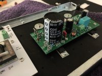
Because the boards are electrically-compatible, they use the same single ended power supply:
+36V,GND. So they have an output coupling capacitor, just like the lottery VFET cards. Here's
one such amp channel board, the capacitor is ten millifarads, 50 volts, snap-in terminals @ 10mm
lead spacing.
The white thing at lower left is a Relentless front end card. Click on the image to see it full
size and undistorted.

What??!? (you may be thinking) Are those connectors I see on the board? Do you mean
the I/O wires aren't soldered???
_
which use semiconductor devices you can buy today from Mouser (i.e. NOT VFETs).
Because the boards are electrically-compatible, they use the same single ended power supply:
+36V,GND. So they have an output coupling capacitor, just like the lottery VFET cards. Here's
one such amp channel board, the capacitor is ten millifarads, 50 volts, snap-in terminals @ 10mm
lead spacing.
The white thing at lower left is a Relentless front end card. Click on the image to see it full
size and undistorted.
What??!? (you may be thinking) Are those connectors I see on the board? Do you mean
the I/O wires aren't soldered???
_
Attachments
Last edited:
The 10.000 uF output cap will be very close to its ESR value already at relative low frequencies so a small bypass cap is "nonsense". If the output cap is audio grade quality it will stay at its ESR at 20 kHz and higher frequencies and then from a point raise in impedance caused by the inductance. I guess the ESR for such a cap is maybe 10-15 mohm? .....try to calculate the impedance of the small bypass cap at 20 KHz and compare to 10-15 mOhm.
as the perfect audiofool i have put a russian 30uf PIO here and it seems it doesn't harm at all

......
What??!? (you may be thinking) Are those connectors I see on the board? Do you mean
the I/O wires aren't soldered???
_
well, I'm not even grumpy when I say that I despise that .........

but, I'm not letting my Despise ruining someone's Happiness

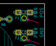
Naturally it is easy and simple to NOT stuff the FastOn 6.35mm (1/4 inch) blade connectors. When you omit those, there are big-fat-wire thru-holes to assist a hardwired and soldered connection. See arrows on image below.
It is also easy and simple to NOT stuff the Euro style screw cage terminal block. Just solder your input twisted pair or input coax cable, to the IN and GND pads where the termblok would go.
_
It is also easy and simple to NOT stuff the Euro style screw cage terminal block. Just solder your input twisted pair or input coax cable, to the IN and GND pads where the termblok would go.
_
Attachments
Very nice work Mark! I for one, totally am in agreement with the use of Faston spade connectors. Mostly for the reasons of easy to assemble, and less mechanical strain on the wires.
I also like the use of Molex KK 2-pin connectors for audio input.
Please spill the beans on this new output stage:

From years back, I have an OS that is also single rail, uses IRFP9240 as ouput in CFP and IRFP240 as CCS, zero global feedback, and cap coupled. Hmm...
Looking forward to seeing more of what your new amp looks like. Thanks for sharing.
I also like the use of Molex KK 2-pin connectors for audio input.
Please spill the beans on this new output stage:
From years back, I have an OS that is also single rail, uses IRFP9240 as ouput in CFP and IRFP240 as CCS, zero global feedback, and cap coupled. Hmm...
Looking forward to seeing more of what your new amp looks like. Thanks for sharing.
Many thanks for the reply, so 50V rating it is to avoid popcorns...
It seems Papa provided already a bypass to that big output cap, so I don't know if it is nonsense, but well, no harm (unless resonance) trying something additional and intermediate, say 10-30uF just to hear how it fares...
It is true that lytic caps have improved a lot re ESR vs frequency, so probably no big expectations
But then at least should I fancy it I know what to try
Many thanks
Claude
Indeed, I have the first edition and like the last sentence of page 350 aswell
Eventhough here the cap is in a different configuration, so I am just thinking out loud. I never had a power amp with DC blocking caps at the output so no clue how sensitive it is but I trust Papa... and that's anyway for future tries, once I enjoyed the pure Mc Coy and it had plenty time to settle
Thanks for all this
Claude
Be sure to study Cordell Figure 19.7 (p.454 of the 2nd edition) and to read the accompanying text.
In the first edition it's Figure 16.7 on page 350.
For those of us who don’t have Cordell’s book, would you mind posting your schematics?
 Please don’t ask a member to make a copyright violation.
 Yep, no prob re sensitivity / efficiency and Fc in relation to Z of speakers, and of course cheap DC protection per se.
I was more considering pure musicality. In short, I never experienced how the quality of an output cap in a power amp could (or not) affect sound quality.
In Cordell's book, for those not having it, discussion is more about caps being used in a PS filter so quite different, my understanding is he would, roughly, use the big cap we have and add a very small cap (as we do) or even a Zobel network. But he also says it might be worth considering an additional ""say" 100uF ish additional cap. All this around key words such as low ESR across wide frequency range, resonance avoidance...
I did that with good effects indeed 3 decades ago on PS caps, but then ESR vs frequency curve of those lytics wasn't as good... and caps weren't directly in the signal path.
As of me, I was merely wondering if people were "playing with bypass caps" in similar builds than the VFET. I do know how it can affect sound in preamps or sources, at lower power levels, but no clue if it makes any real sense in our case. Well noting I am just wondering at this stage and the amp will be built strictly as per Papa's recommandations first.
All this is just new to be, coming from Class AB push pulls rather than SET power amps...
Claude
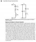
Here's Figure 16.7 of Cordell's first edition, which is out of print. Bob and I are friends and I'm sure he will be delighted to see one of his figures displayed here under fair use (Wikipedia citation)
If you replace Cordell's phrase "reservoir capacitor" with the phrase "loudspeaker output coupling capacitor", you can begin to appreciate the potential danger when Joe Bob DIY slaps down an audiophile grade, $20 bypass capacitor, without performing careful circuit analysis.
_
If you replace Cordell's phrase "reservoir capacitor" with the phrase "loudspeaker output coupling capacitor", you can begin to appreciate the potential danger when Joe Bob DIY slaps down an audiophile grade, $20 bypass capacitor, without performing careful circuit analysis.
_
Attachments
Our VFET amp has a 0.33 uF WIMA cap to bypass the 10 mF output cap?
But difficult to see it has much bypass capability at 20 kHz compared to the 10 mF cap and we don't need frequencies in the MHz area to the speakers?
The impedance for 0.33 uF is 24 ohm at 20 KHz and 10 mF cap must be around 10-20 mOhm ESR value unless it has a lot of inductance?
But difficult to see it has much bypass capability at 20 kHz compared to the 10 mF cap and we don't need frequencies in the MHz area to the speakers?
The impedance for 0.33 uF is 24 ohm at 20 KHz and 10 mF cap must be around 10-20 mOhm ESR value unless it has a lot of inductance?
- Home
- Amplifiers
- Pass Labs
- DIY Sony VFET Builders thread