Here is another good option for getting custom metals in the US.
https://pages.onlinemetals.com/index.php/email/emailWebview?md_id=1892
https://pages.onlinemetals.com/index.php/email/emailWebview?md_id=1892
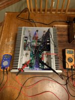
I just realized that the meanwell psu adapter that I am using rated 36vdc is having 2 pin rather than 4 pins which was being sold in the diyaudio store as well as the kits that came with the Nelson. Now I did the wiring as below and still I get a good amount of thump sound when I switch Off the amp but no thump sound while switching On. I see that the 4 pin version adapter might be able to handle the inrush current much better than 2 pin model and is that the case that even with the below wiring diagram I am not able to get rid of the thump? Or using some thick wires for all the power lines might help here!

in my experience the 2 or 4 pin just refers to an internal bank of connections. [Mine has 3+3] They are connected to each other, the only advantage is that the sense line of the output is connected there (ensuring lowest impedance) , but for us using constant current that is all trivial. You say the thump is on switch off. IMHO the inrush has nothing to do with it.
The thump has to do with other things; there is an anti-thump circuit.
The thump has to do with other things; there is an anti-thump circuit.
Hmm makes sense then I am using the wiring as in the above pic of O+, O+ connected to the output of the amp boards and then to the speaker binding posts. I do not get any turn on thump but yes turn off thump is still their with the above wiring. I am not using any speaker protection circuit/board in my builds either so just the Tuba smps filter board.in my experience the 2 or 4 pin just refers to an internal bank of connections. [Mine has 3+3] They are connected to each other, the only advantage is that the sense line of the output is connected there (ensuring lowest impedance) , but for us using constant current that is all trivial. You say the thump is on switch off. IMHO the inrush has nothing to do with it.
The thump has to do with other things; there is an anti-thump circuit.
I am using the TUBA psu filter board with the store kit minus vfets as I had a pair of vfets with me. I also have the previous iteration of the psu filter board of Mark as well used it earlier. My build pics are in post #411Are you using the TUBA psu board or the stock psu that came with lottery amps?
And where exactly did you add this 10000uf capacitance?OK. What I use on my 2SK182 build is: a high value capacitor of 10.000 uF, so when the power goes down, the Vb drops 'slowly enough' not to give a bump. My bias is stabilised too, for a long settling time.
That is a different (but simple) approach.
Before the amplifier, that is, mounted somewhere else on the chassis. It should be easy to give it a try.
Some SMPS will hiccup untill it is finally charged; that will take a few cycles more.
My SMPS has no problem.
You could also have a 2 ohm resistor in the lead, enough to slow charge and enough to have as a load for discharge (at 2,5 amps is 5 volts) or cross that resistor with a diode. I have a capacitor bank from an airplane that does that . . . at 400V
Finally finished my P channel 2sj18 build, Mark’s FE the scourge. Filter is Mark’s THESEUS-Power supply filter, works great, the amp is quite and no speaker thump. I got a chance to listen to last night for an hour and sounds wonderful! Running lowthers in a pair of big fun horns with the amp. Built the amp on my breakfast table. The vfet were NOS and was still in the Sony packaging. I still have the N channels that were packaged with the P channels. They were backup for the Sony Ta-4650 I had. I will do more listening this weekend. I love the chassis.

Tony
Tony
Attachments
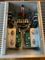
Yesterday I finished for 98% my build of the 2SJ28 version. I have 0,82 ohm + 0,12 ohm = 1 ohm. The DC current is 1,3 Amp on both sides. The amp stays relatively cool (good in these times of hot-houses.)
I have the Vb at 36Volts like the specs say and I have an 'internal' powersupply (Meanwell RSP-200-36), that is placed on the bottom plate. Also on the bottom is a 12V supply for the filament of my driver tubes. It all fits nicely.

I have a 6 amp double choke in the PS, the thing with the red tape on it.

My driver is based on a PCC88 tube running in parallel. Just on 40Vb. And it gives 30Vpp and still -72 dB distortion.

The sound is awesome.
to do:

It's not as fancy as the other builds. But for me it looks great.
I have the Vb at 36Volts like the specs say and I have an 'internal' powersupply (Meanwell RSP-200-36), that is placed on the bottom plate. Also on the bottom is a 12V supply for the filament of my driver tubes. It all fits nicely.
I have a 6 amp double choke in the PS, the thing with the red tape on it.
My driver is based on a PCC88 tube running in parallel. Just on 40Vb. And it gives 30Vpp and still -72 dB distortion.
The sound is awesome.
to do:
- There is a little thump at power-down. I still have to make a relais to short the output (bleed the capacitor) when I shut off. Probably I need an extra buffer capacitor too for the driver, to give it 5 secs power reserve (1.000µF should be enough; the driver running at 15 mA) - now it reacts to the switch-off with a short pulse I think.
- Make a distortion analysis.
It's not as fancy as the other builds. But for me it looks great.
Those should be 2SK60 / 2SJ18 so yes they will work. You can double check numbers by flipping the receiver over and looking through the mesh on the bottom.sorry if this is obvious to others... can the vfets from a Sony 4650/5650 be used to make this vfet amp?
Sorry to bother you with a question about my own build with a folded cascode. Initial: great. But as things go on, getting worse. I expect trouble in the 'folding'. What happens is that I see more and more power supply noise. I have a PS brick inside the cabinet.
What could be wrong?
The darlingnot folded cascode driver: <0,1%

1 kHz, 0,2% distortion, of the output on 8Ω but I can see a lot of spikes.

Just the bare output with a shorted input of the SIT:

I have a simple ∏-filter with 0,250 mH and 330 µF//10.000µF (the latter to stop the thump and get gracefull=slow shutdown) but the earth line seems to keep the noise.
The driver circuit:

It gets worse is my stupid impression.
Maybe the gate of the J74 I use gets kicked around?
Does the choke pick up noise from the Meanwel RSP 200 36V? [I shorted the input of the SIT cards to earth by shorting the choke, no big improvement, just less HF noise, the spikes and debris are cleaner], measured now as 6 mV RMS . . .
It sounds as 'lispeling' in the speaker, a faint two-tone melody noise on the background (93dB speakers) with the ear near the speakers. I have two bicks, 36V and 12V the latter for the filament.
I am willing to give up the folded cascode that on its own sounded (and sounds) good.
As to start/stop: the choke gets 7 Vdc across it. The gate of the SIT should be able to handle that shutdown without a problem. [I AM worried I am distroying the gate. On the other hand, I set the DC to 19,85 volt on the drain, and it still is, so no gate current change.] The shutdown is now very gracefull (with //10.000 ΩF on PS)
I used the wire layout like on 6L6's building guide, so no central earth.
any help appreciated. Like said, I feel stupid and twice that because I like to 'invent' things. Why am I allways having things working, then improve it a bit and it breaks down? Sysyphus is alive and kicking me.
What could be wrong?
The darlingnot folded cascode driver: <0,1%
1 kHz, 0,2% distortion, of the output on 8Ω but I can see a lot of spikes.
Just the bare output with a shorted input of the SIT:
I have a simple ∏-filter with 0,250 mH and 330 µF//10.000µF (the latter to stop the thump and get gracefull=slow shutdown) but the earth line seems to keep the noise.
The driver circuit:
It gets worse is my stupid impression.
Maybe the gate of the J74 I use gets kicked around?
Does the choke pick up noise from the Meanwel RSP 200 36V? [I shorted the input of the SIT cards to earth by shorting the choke, no big improvement, just less HF noise, the spikes and debris are cleaner], measured now as 6 mV RMS . . .
It sounds as 'lispeling' in the speaker, a faint two-tone melody noise on the background (93dB speakers) with the ear near the speakers. I have two bicks, 36V and 12V the latter for the filament.
I am willing to give up the folded cascode that on its own sounded (and sounds) good.As to start/stop: the choke gets 7 Vdc across it. The gate of the SIT should be able to handle that shutdown without a problem. [I AM worried I am distroying the gate. On the other hand, I set the DC to 19,85 volt on the drain, and it still is, so no gate current change.] The shutdown is now very gracefull (with //10.000 ΩF on PS)
I used the wire layout like on 6L6's building guide, so no central earth.
any help appreciated. Like said, I feel stupid and twice that because I like to 'invent' things. Why am I allways having things working, then improve it a bit and it breaks down? Sysyphus is alive and kicking me.
Hi `central = star. Now I have each channel a twisted pair from plug --> left driver input; then twisted pair --> SIT output card. Earth is connected on driver and output card. Hence there can be a loop because the driver board is also connected --> earth and output too. Star would break the multiple connections somewhere.
I did a quick experiment, attached a separate Meanwell 12V power for 12V filament, the noise only inreased. So I get the impression it is the filament/cathode barrier that is transmitting noise . . I'll try make a simple filter around a LM317 stabiliser.
I did a quick experiment, attached a separate Meanwell 12V power for 12V filament, the noise only inreased. So I get the impression it is the filament/cathode barrier that is transmitting noise . . I'll try make a simple filter around a LM317 stabiliser.
- Home
- Amplifiers
- Pass Labs
- DIY SONY VFETS pt 3 - Got VFETs?