I'll do the cutting.
In the mean time I followed the 'noisy filament' path. I before in the noisy state had connected the 12.6V minus to the earth. No elevated filament.
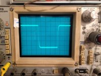
Now I connected the minus of the filament PS through a 10KΩ to the V+; the connection is also attached to earth via a 6.8µF capacitor. The tube is elevated to 45V average, like you would do in a real tube amplifier (with a real driver with real 80-100V power supply that is") ) I can say: very silent now.
) I can say: very silent now.
Below a 100mV 3kHz square wave in 8Ω. So this looks good.
In the mean time I followed the 'noisy filament' path. I before in the noisy state had connected the 12.6V minus to the earth. No elevated filament.
Now I connected the minus of the filament PS through a 10KΩ to the V+; the connection is also attached to earth via a 6.8µF capacitor. The tube is elevated to 45V average, like you would do in a real tube amplifier (with a real driver with real 80-100V power supply that is
) I can say: very silent now.Below a 100mV 3kHz square wave in 8Ω. So this looks good.
Attachments

that was the next thing I planned to suggest
in some cases that nasty diode transfer characteristic between heater and cathode is real troublemaker
better make proper voltage divider, with 1mA through, to avoid results of toob mood

so 10K-33K, lower one bypassed with 1uF upwards
Thanks Zen, this really helped me in this moment of peril.
OK I'll do that, 10K--> 36V and 33K --> earth so the mean filament voltage is 35 v approx.
In the mean time I have disconnected the outgoing earth from the driver board twisted pair. The noise dropped from about 1 mV RMS on the output to less than 0,1 mV RMS. Now that is something!
I had for God's sake also taken 10 pF across the 215K feedback of the driver (it did reduce the noise - but also a BW that dropped to 50 kHz) now it is a 6 Hz-120 kHz again.
I have Tesla PCC88 can upgrade to a blue topped PCC88 that has almost double mu and lower Rplate. I have tried E90CC but it had slightly more 3rd harmonics.
Anyone interested in the ‘lottery’ chassis for their VFETs have a look at:
https://www.diyaudio.com/community/threads/vfet-chassis-limited-production-run.391308/#post-7149307
https://www.diyaudio.com/community/threads/vfet-chassis-limited-production-run.391308/#post-7149307
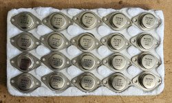
Looking for Sony VFETs / SITs? Curve-matched parts are available here: 2SK82 and 2SJ28 with curve traces
I don't know how my pair of 2SK60 VFETS measure/rank/match but I guess it might be useful to find out. Can anyone give me a steer on doing that? I did do a quick search of the forum to see if I could find something myself but didn't turn up an obvious match - maybe I just got the search criteria a little wrong. Cheers.
You can use the 2sk82 circuit in the diagram here originally posted by Papa:
https://www.diyaudio.com/community/threads/how-can-i-match-v-fets.307603/#post-5075546
The important thing is to start with the Vgs at the 'lowest valule' (-19V) and slowly increase it while monitoring the current by measuring the voltage across the 1R resistor.
https://www.diyaudio.com/community/threads/how-can-i-match-v-fets.307603/#post-5075546
The important thing is to start with the Vgs at the 'lowest valule' (-19V) and slowly increase it while monitoring the current by measuring the voltage across the 1R resistor.
@nautibuoy : The bias voltage needs to be in place before you apply V+ voltage to the vfet. For the bias voltage, you can just use a couple of 9V cells in series.
If you only have two VFETs, don't worry about matching. The bias voltage is adjustable so a wide range of Vgs will work in the circuit.
None of the SITs/VFETs in my diy amps are matched and that doesn't affect my enjoyment of their sound, even if the left channel may measure a bit differently from the right channel with respect to harmonic distortion.
Matching of Vgs will not ensure identical performance. Curve matching is needed for that.
If anyone wants some more Edcor PC600-15K transformers, as used in the Sony VFET front ends {including Scourge and Bulwark}, I'm giving away a set of nine of them for free (but you pay $17 postage). And you have to un-solder them from obsolete PCBs. Here is a link to the message in the Swap Meet.
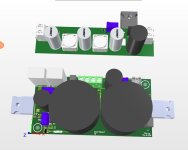
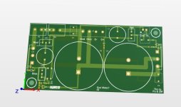
Having some vfets around I decided to build this amp on some proto pcbs. I was impressed about the sound so I decided to draw a pcb for it.
In the meantime Mark designed the AmyAlice filter for which I drew a pcb too. I added a extra cap multiplier to make it suit my needs.
I will have the pcbs in a few weeks so the rest of the fun still has to come.
A big thanks to Pa, ZM and Mark!
In the meantime Mark designed the AmyAlice filter for which I drew a pcb too. I added a extra cap multiplier to make it suit my needs.
I will have the pcbs in a few weeks so the rest of the fun still has to come.
A big thanks to Pa, ZM and Mark!
Attachments
- Home
- Amplifiers
- Pass Labs
- DIY SONY VFETS pt 3 - Got VFETs?