Hi Greg,Ryan,
Will there be another board run? Sorry if I missed you already answering this.
If anyone here does. It have my build D3 build guide please let me know.
Cheers,
Greg
I still have a few PBCs left over from the last batch, not sure if ill get anymore made up at this stage.
Nice.Here is a link to a video clip playing a percussion track before adding supercaps to +-5v supplies of 1541a
Now the same track after adding supercaps
Just recorded using android phone with built in mics. Not nearly the same as being there, but I think with headphones you can get a sense of the difference.
As I mentioned in the other thread, I am having a positive experience with parallel LTO batteries and Maxwell Ultracapacitors powering my TDA1541a.
The Maxwells are either 310F/2 (2 5V supplies) or 350F/6 (-15V supply)
So, a net capacitance of 155F for +/- 5V and 58.33F for -15V… substantially more than the 1.5F you are using.
So, it’s great to know there’s a much lower threshold of Farads for a positive difference than I might have suspected otherwise.
cheers,
Chris
Is it correct that these are 2.7v cells individually or?Nice.
As I mentioned in the other thread, I am having a positive experience with parallel LTO batteries and Maxwell Ultracapacitors powering my TDA1541a.
The Maxwells are either 310F/2 (2 5V supplies) or 350F/6 (-15V supply)
So, a net capacitance of 155F for +/- 5V and 58.33F for -15V… substantially more than the 1.5F you are using.
So, it’s great to know there’s a much lower threshold of Farads for a positive difference than I might have suspected otherwise.
cheers,
Chris
I wonder what the ESR of 6 of these in series would be, could be approaching more than some regs.
Actually never mind, you are not using them in series with the supply but as bypass, but still they seem to be in the 100s miliohms range.
And operating so close to their breakdown voltage means leakage current is probably substantial (and especially since electrolytic).
The lead spacing on the one wlowes has is massive and closes a large loop so i wonder what the inductance of this is, or if this will tend to create tuned circuits with other caps in parallel.
Wether all this matters or not is up in the air, i guess this is not the advertised main benefit of doing this?
It is not too expensive so might be a fun experiment...Just watch not to short them somewhere in the case by accident..
Iancanada & Greg in Mississippi did some subjective listening tests and reported best sound from the bigger 300+F caps. I believe there is an 80/20 rule. I suspect I get 80% of the benefit from these little 1.5F 5V caps. I like them because they are cheap, and you can put them really close to the consumer. I've soldered them right on the power leads to clocks and various parts of the reclock chain. I am using old ones I harvested from other applications. Point is, even the worst of them are an improvement over the best filtered power supply using the lowest noise regs. For the SOTA, use Ian's circuit with the big ones for $100s per rail or get 80% with sub $10 per rail and they'll fit in your existing chassis. ")
Thanks for the advice, I replaced the C19 100uF / 25V and C22 220uF / 25V and wound the resistors 35 ohms, the sound has improved a lot and the dynamics is more pronouncedHi,
I use Elna cerafine and silmic in these positions. I like them more than the oscon.
If your problem is too little dynamics than maybe your IV resistor value is too low. If they are too low you will lose dynamics. In most cases 34ohm is optimal But you can go higher up to around 60ohm, your distortion will also increase though.
Attachments
Is it correct that these are 2.7v cells individually or?
I wonder what the ESR of 6 of these in series would be, could be approaching more than some Actually never mind, you are not using them in series with the supply but as bypass, but still they seem to be in the 100s miliohms range.
hello @Makone
They are 2.7V. The BCAP0350 Maxwells are rated max ESR of 3.2 milliohms each, so not so bad even in a series of 6.
The BCAP0310’s are even better at 2.2 milliohms.
Here’s a pdf comparison chart on the 2 from Maxwell. I think at least the 350F is discontinued now but readily available from eBay.
I’ve been using Ultracapacitors in some form or the other for a year or two now (time flies?) but getting this size Ultracapacitor out from behind relays to directly connect to the load is new.
Some of the larger LTO batteries have extremely low ESR as well and I have a couple to experiment with.
As some others seem to, I suspect there is more going on than a reduction in ESR with the results we hear with supercapacitors, though.
@wlowes
I hear you …. I also have a trove of “coin” 1F-4F 5.5V and 6V supercapacitors I have used here and there, usually to supplement a LFP 3.3V supply.
cheers,
Chris
By the way, anyone thinking of using, especially, these larger Ultracapacitors, should check out the absolute maximum current and short circuit current for these 310F and 350F versions.
comparison table pdf here
And many in Ian’s audience are using 3kF versions.
Scary dangerous. It has me wondering what kind of extra safeguards I might add to keep one of our pet rats from scurrying across a TDA1541a board as it converts 1s and 0s to jazz fusion or art rock via multi amp active crossover system.
cheers but not fears- just rational safety measures,
Chris
PS- tip of the day for others using Arduino/RaspberryPi system control - I have found these smaller 1F-4F 5-6V supercaps are splendid for galvanically isolated, relay-controlled “flying capacitor” voltage measurement … so the system can better self-regulate recharging, shut down in an over or under-voltage situation, manage current-controlled charge-up of supercapacitors, etc. They are connected in parallel to the PS across two relays which switch to move them over to an Arduino analog input for voltage measurement every so often… and, as opposed to “regular” capacitors, these hold the voltage long enough to allow multiple measurements to be averaged for better accuracy.
PPS- @ryanj I may also be interested in one of the remaining boards if you still have enough and shipping costs to East Coast US makes sense.
Last edited:
Hi Walter,Likely a stress test for Q1 & Q2. Maybe Ryan has an idea what will happen. Charging a large cap sucks some power for 2 mins.
I couldn't get the simulation working with such a large capacitance so im not totally sure how it will behave. But no matter what the CCS in the path of the zener string will always stay constant at 135mA. So if anything while the caps charge up CC1 will have a higher voltage drop across it so will have to dissipate more power during startup. Might be enough to put a heat sink on CC1. (Try at your own risk.)
I have 25 D3 PCBs left.
Thanks Ryan. Perhaps some brave soul will try (with spare parts ready). I suspect 317 has some built in protection. It will take a while to come up to speed, so it only makes sense if you leave it under constant power. Iancanada's Uconditioner is another option as it preloads the supercap and the power supply only keeps it charged up if I understand correctly.
This article says the key point is to never let the voltage difference on 317 input to output exceed 30v. So should be ok. https://electronics.stackexchange.com/questions/148340/how-to-protect-lm317-from-output-short
These are pretty nice. I also suspect you're right its not related to ESR. I might experiment with this as well now just to see if something can be gained...hello @Makone
They are 2.7V. The BCAP0350 Maxwells are rated max ESR of 3.2 milliohms each, so not so bad even in a series of 6.
The BCAP0310’s are even better at 2.2 milliohms.
Here’s a pdf comparison chart on the 2 from Maxwell. I think at least the 350F is discontinued now but readily available from eBay.
I’ve been using Ultracapacitors in some form or the other for a year or two now (time flies?) but getting this size Ultracapacitor out from behind relays to directly connect to the load is new.
Some of the larger LTO batteries have extremely low ESR as well and I have a couple to experiment with.
As some others seem to, I suspect there is more going on than a reduction in ESR with the results we hear with supercapacitors, though.
Hi,Thanks for the advice, I replaced the C19 100uF / 25V and C22 220uF / 25V and wound the resistors 35 ohms, the sound has improved a lot and the dynamics is more pronounced
Good to see your report: have fun listening to this awesome DAC design!
Hi,
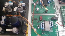
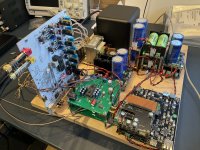
I did a comparison between the D3 in balanced mode with Sowter opt’s, and the Aya5 dac board.
I made a “Quasimodo” setup with the Aya5 board perched vertically next to the D3 and connected with the simultaneous output of the I2S-SIM pcb. In this way the streamer is exactly the same and I can easily change between the two DACs.
The Aya5 has been running in for about 10 days on my work bench before testing and I used an S1 dac chip (not on the picture) for fair comparison.
When I started listening, the difference was immediately very clear; the Aya5 is not up to the level of a balanced D3. The difference is big and this puzzled me.
The Aya5 is less open, more congested, the highs are much less clear and detailed. On the other hand, the low frequencies have a bit more power and drive; this is most probably due to the low output impedance of the IV stage (and higher gain) compared to the opt. Note that the dacs are directly feeding a volume transformer and these are sensitive for high output impedance, so it does matter here.
The overall sound of the Aya5 is a bit dark.
The D3 has a much more 3d presentation with lots of space between the instuments, all instruments can easily be followed even if with crescendo passages. The decay and harmonic structure of the instruments is much better. The dynamics are better.
I did not expect such a big difference, I still think the Aya5 is good value for the asking price but a balanced D3 is clearly quite a step higher!
When I have the time I want to do some modifications to the Aya5, there is some improvement possible on the power supply lines and I need to check what else I can identify as a weak spot.
Regards,
Attachments
D
Deleted member 537459
I was also surprised of the outcome. I have not done any modifications to the Aya5 board yet.Thanks for the report Supersurfer.
I'm surprised by your findings, I thought it would have been a close contest. I wouldn't have though such an obvious difference. Maybe the Aya needs some fine tuning. What DEM frequency is the Aya running at?
The capacitor between pin 16-17 is 470pf and 100nf decoupling on DEM pins.
The board can also be executed with active DEM clocking but I hesitate if I would do all the effort if the difference is this big.
@ilgavro I have not tried the Bisesik transformers. Have you tried the Sowters?
- Home
- Group Buys
- DIY TDA1541A PCB "D3"