What is the model of cap? If it shorted, then is it a foil cap? A metallized cap may have just made a hole in the metallization and cleared the fault. Overvoltage would be more likely than overcurrent if it is foil. Or perhaps it got overheated from being close to the resistor and/or rectifier? Do the melt marks line up with something it was resting against?
Edit: Attaboy! Wait, does that come off wrong if I'm younger than you?
Edit: Attaboy! Wait, does that come off wrong if I'm younger than you?
Hard to read the damned thing with my old eyes. I looked through my notes and I didn't record it.
After your post I dug it out of the trash and it does read correctly at 10n, which it should be. I don't know if something shorts with power or what. Strange, but not enough to dig further. It's working.")
After your post I dug it out of the trash and it does read correctly at 10n, which it should be. I don't know if something shorts with power or what. Strange, but not enough to dig further. It's working.
hey thompsontechs, there are two classes of diagnosis with the dim bulb, first is when the bulb lits up full bright, it means shorted output trannies, and in case of first time livening up a reversed positions....second, if the dim bulb tester is very dim but you have a huge dc output offset voltage, that is a sign of resistors opening up, or trannies leaked....so recognizing which one you have is a step in the right direction....very seldom that you have the same scenario at the same time, but this is not to say it can not happen...
The Badger is singing once again! Nice to figure it out with no help too. can I get an ATTABOY?
congrats...
Here are my gerber files and calculation sheet
male connector
10X BNC male plug solder PCB mount RF coxial converter connector | eBay
female connector
WM5517-ND
other info should be here
QA401 - Differential measurements with attenuation - QA401 - QuantAsylum Forum
and I believe you have everything else
Okay, I got the pcbs made and am looking at the bnc male female and I am unsure how these get soldered in as it looks like I will need to remove some legs, perhaps on the diagonal so that all have proper all three on the board. Also, what values and positions for the resistors?
Thanks
JT
EDIT Okay, I see if you remove 2 legs from the male it fits the two open holes.
Last edited:
Okay, I think I've got it now, you are using R1 (3 pads in series to get the value you want) In this case 98,785.23 Ohms. You missed your target by half an ohm. Cool and for R2 you just used one resistor that got you very close, so no need for adding more and you just shorted the unused ones to complete the circuit.
I'm clear, I think, except for the R1d ? Where is the R1d?
I'm clear, I think, except for the R1d ? Where is the R1d?
Last edited:
You've got it.Okay, I think I've got it now, you are using R1 (3 pads in series to get the value you want) In this case 98,785.23 Ohms. You missed your target by half an ohm. Cool and for R2 you just used one resistor that got you very close, so no need for adding more and you just shorted the unused ones to complete the circuit.
I'm clear, I think, except for the R1d ? Where is the R1d?
R1d from Excel was just a extra column so I could put the next actual resistor size in to see how far I was out on the actual required R1. The last column to look at is diff R1 it is just how far off you will be from the actual calculated R1 value. At the end of the day just use the R1abc to get as close as you can to R1. Measure each of your resistors and put the values in as most resistors as you know won't Measure there nominal value.
May sure you use some kapton tape to prevent the outer ring on the BNC from shorting to ground.

When it all done. Use a Dual rail DC power supply. Set it to say so you get +12, 0, -12 and attach the +12v to the inner pin on the input BNC, attach the -12v to the outer ring of the input BNC, attach the 0v to one of the outer rings of the output BNC.Okay, I think I've got it now, you are using R1 (3 pads in series to get the value you want) In this case 98,785.23 Ohms. You missed your target by half an ohm. Cool and for R2 you just used one resistor that got you very close, so no need for adding more and you just shorted the unused ones to complete the circuit.
I'm clear, I think, except for the R1d ? Where is the R1d?
Now use you DMM and measure each of the outputs. Put the negative DMM lead on the output BNC outer ring and switch the positive DMM lead between the inner pin on each of the output BNC's use the trimmer to get the exact voltage on each.
Last edited:
You've got it.
R1d from Excel was just a extra column so I could put the next actual resistor size in to see how far I was out on the actual required R1. The last column to look at is diff R1 it is just how far off you will be from the actual calculated R1 value. At the end of the day just use the R1abc to get as close as you can to R1. Measure each of your resistors and put the values in as most resistors as you know won't Measure there nominal value.
May sure you use some kapton tape to prevent the outer ring on the BNC from shorting to ground.
View attachment 957678
Still don't follow that then, because your values for R1 are 91k + 5.1k + 680R = 96.780k so you are off by 5.23ohm and not .53 ohms. ???
Still don't follow that then, because your values for R1 are 91k + 5.1k + 680R = 96.780k so you are off by 5.23ohm and not .53 ohms. ???
That's right but diff R1 assumes that you use 4 resistors on each side of the Voltage divider. but this was taking things to far 3 is enough.
Okay, and since you would have had to do some crazy small package to get a 4th in series, or got into crazy *** parallel with one of them... just call it close enough and move on. After all this is only about attenuation and as long as they are balanced and you know where that fall to enter in your db then good enough.
Exactly... Good luck with your testing. Please post your results. You should be able to set your output to -0.5dbv nowOkay, and since you would have had to do some crazy small package to get a 4th in series, or got into crazy *** parallel with one of them... just call it close enough and move on. After all this is only about attenuation and as long as they are balanced and you know where that fall to enter in your db then good enough.
Had to dosome brush up on series parallel, haven't done any of that in 35 years.
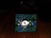
Hope I got it right. :O I had to do that to make it work out with what resistors i had. If my calc are correct, it should come out to approx 96,820 give or take an ohm or two on R1 and R2 is 2,250 give or take an ohm.
I haven't calibrated it yet... enough for today, it's time for a cold one and some music. Will get back to you tomorrow.
Attachments
Last edited:
one thing to remember when paralleling resistors, the combined values will always be smaller than the smaller of the two, like say if you parallel a 10k with a 4.7k, the resulting value is smaller than 4.7k for sure..in this case 3197ohms.....this is a rule of thumb....Parallel Resistance Calculator - Electrical Engineering & Electronics Tools
12v input and the + and - outputs of the atten. I worked out the voltage divider, but I'm not sure.
I'm getting + - 139.6mV after calibration. When I work backwards from that it seems a bit low.
Looks like you have an attenuation of -38.68 dB
The math is 20 x log(0.1396/12)
But then you have an extra -6dB of attenuation added by the QA401.
So you will be at -44.68 which is to high.
I'm doing this off the top of my head i haven't checked my spreadsheet but I think. Your target should be -28.56dB then an extra -6 db will be added by the QA401 so 34.56dB or there abouts.
My target is
80 watts output and -0.5dbv input
20 x log(0.9441/25.2982)
Equals -28.56dB
Check my spreadsheet those numbers should be about right.
Last edited:
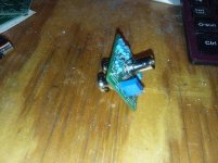
Worked the divider out and the readings just didn't seem right. I checked everything and then had a thought and check my bench supply. I have little to no neg output there.
I had an old project one i made in EET some 35yrs ago. i fired it up, sure enough stil worked. I tweaked it up to -+ 12v and hooked everything back up.
Now I get 279.69mV which is about what the reverse divider equation came out to as well.
So that looks to be -32.7 which is still on the high side.
I had an old project one i made in EET some 35yrs ago. i fired it up, sure enough stil worked. I tweaked it up to -+ 12v and hooked everything back up.
Now I get 279.69mV which is about what the reverse divider equation came out to as well.
So that looks to be -32.7 which is still on the high side.
Last edited:
- Home
- Amplifiers
- Solid State
- diyAB Amp The "Honey Badger" build thread