Printed a schematic out and gave the entire thing a colonoscopy. ") I think I have it in order now, but I will need to get everything back in and fire it up to be sure. D1 or D2 were toast on both boards. I could have speced them wrong or something nasty at the input.
I think I have it in order now, but I will need to get everything back in and fire it up to be sure. D1 or D2 were toast on both boards. I could have speced them wrong or something nasty at the input.
Q9 was gone for sure. to be safe, as I said above, I basically checked everything, to the best of my limited ability, and I hope I caught everything.
I was getting some damn strange ohm values, but after I replaced Q9, R25, D1 and D2 the values looked much better. I pulled a lot of components for testing too. If something didn't look right to me I pulled it and tested it properly. Marking it off the schematic as I went.
Both CSS and VAS were okay in fact, it looks like the only transistor which got hurt was Q9. I'll mount it all back in tomorrow defaulting back to pre biasing and with a bulb on it.
If it all works out, fingers crossed, this will be a good learning experience for me... especially since ya'll gave me some tough love in the help dept.
JT
I think I have it in order now, but I will need to get everything back in and fire it up to be sure. D1 or D2 were toast on both boards. I could have speced them wrong or something nasty at the input.Q9 was gone for sure. to be safe, as I said above, I basically checked everything, to the best of my limited ability, and I hope I caught everything.
I was getting some damn strange ohm values, but after I replaced Q9, R25, D1 and D2 the values looked much better. I pulled a lot of components for testing too. If something didn't look right to me I pulled it and tested it properly. Marking it off the schematic as I went.
Both CSS and VAS were okay in fact, it looks like the only transistor which got hurt was Q9. I'll mount it all back in tomorrow defaulting back to pre biasing and with a bulb on it.
If it all works out, fingers crossed, this will be a good learning experience for me... especially since ya'll gave me some tough love in the help dept.
JT
Hi Tony,
I have a couple different versions of that thing. It doesn't measure leakage properly as it isn't sensitive enough.
I don't use them anymore as my old tools told the truth and were more accurate.
If you are attempting to match transistors, the two must be at the same temperature. Period. So make your own diff pair circuit up. Measure the difference between collector voltages using the meter as a null indicator.
When you don't know any better, it does appear to work well. That's the danger of those silly things. They work fine in a gross sense. Just like the beta tester in a cheap meter. Why ever would you expect them to be accurate??
why do you even have those things?
i have three versions of those that i use alternately...that is a go no go device, measured hfe, identified leads, measure cap esr, capacitance and inductance....even tells you if your transformer has went bad....
i know i am not convincing you in anyway, but it worked for me very well...
ultimately the final test is a working amp, and that to me is what counts in the end, how to get there, there are a lot of ways...
the thing i like most is that they are cheap....full stop...
btw, matching transistors, close enough hfe readings are all that is often required, worked for me too, precision need never be in the ppm regions....i built a lot of Leaches and amps to know better...
Last edited:
Printed a schematic out and gave the entire thing a colonoscopy.
Q9 was gone for sure. to be safe, as I said above, I basically checked everything, to the best of my limited ability, and I hope I caught everything.
I was getting some damn strange ohm values, but after I replaced Q9, R25, D1 and D2 the values looked much better. I pulled a lot of components for testing too. If something didn't look right to me I pulled it and tested it properly. Marking it off the schematic as I went.
Both CSS and VAS were okay in fact, it looks like the only transistor which got hurt was Q9. I'll mount it all back in tomorrow defaulting back to pre biasing and with a bulb on it.
If it all works out, fingers crossed, this will be a good learning experience for me... especially since ya'll gave me some tough love in the help dept.
JT
the key here is to identify all busted parts and to replace "all" because if you miss out on one, you definitely still have problems...
that dim bulb is truly a life saver....
Hi Tony,
Hey, fair enough.
Do me a favor and build the transistor matcher I designed. It isn't expensive and makes a good project. Its in one of the Adcom GFA-565 threads near the end. Many people have built it and there were at least two boards designed for it.
sorry but i do not recall those, any links or documentations you can pass to me?
diyAB Amp The "Honey Badger" build thread
I think his matcher was spun off into this thread, I haven’t personally checked the files at this point though.

sorry but i do not recall those, any links or documentations you can pass to me?
I think his matcher was spun off into this thread, I haven’t personally checked the files at this point though.
not at all, any successful badger build will depend to a large extent on being able to grade and match ltp trannies, i would even go so far as matching current mirrors and cascode trannies...
i would certainly love to get my hands on gerbers.....jlpcb boards are just a week away from my side of the pond....
i would certainly love to get my hands on gerbers.....jlpcb boards are just a week away from my side of the pond....
see if this gets you what you need Tony. Had to go down the rabbit hole to find these, apparently they were posted to a long since closed Dropbox and luckily got reposted.
Attachments
Hi bullittstang,
Perfect! Thank you for finding that project. Chris's board works well. He sent me a few boards, and I gave them to people that could use them, so I know his board works.
I designed mine decades ago and still have the worn out perf board one. Then I designed a PCB and have that . Use it all the time. I am more than willing to answer questions on it along with build details.
For the collector and base resistors I used Dale 0.1% resistors. This jig will allow you to get matches within 1% fairly easily. The test points can be reduced to the collectors and supply voltages. That means three per polarity.
When you buy the sockets, use quality units bought from the normal sources. I tried several samples from Ebay and Ali, they made using the jig very difficult and frustrating to use, so do not skimp here. There are four positions that allow you to test all the base configurations, Pro-Electron, JEDEC and the Japanese standard - forgot the acronym.
Stick the pair together, cover with close fitting foam, and cover it with a box. Transistors are very temperature sensitive and air currents will cause the readings to drift. I find that a 3 mA tail current settles quickly compared to lower settings. The tail currents are adjustable so you can test at your design current (handy). You do have to wait until the temperatures equalize.
I presort the transistors using something like what Tony uses now, or a multi-meter with transistor test. Then once you begin running the parts through you will see how far they are apart even though you matched them. It is sobering to see.
Tightly matched LPTs will reduce distortion and cause the DC offset to be very stable. You can ignore DC servos, or use the old style of injecting a current with a trim pot. Either tends to sound better than some servos. Filtering the output ofa servo sounds better than the normal practice of running the output into the feedback network through a resistor. Actually, sifting the predrive DC level sounds the best because you are balancing the LPT instead of forcing an imbalance.
Anyway, tight matching is worthwhile and allows the circuit to perform to its best. There are other tricks, but this is the big one.
As I said, I will happily answer questions on it.
-Chris
see if this gets you what you need Tony. Had to go down the rabbit hole to find these, apparently they were posted to a long since closed Dropbox and luckily got reposted.
thank you kindly, will have some boards made...
i also pick and choose trannies based on measured and displayed reading, naturally you want to use those with big hFE readings, as to those that are not selected, they are still useable in some other positions not requiring closely matched or high hfe readings..
afterall this is a honeybadger build thread...
afterall this is a honeybadger build thread...
Last edited:
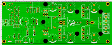
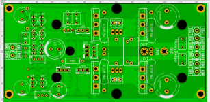
What do you think, which type of amplifier board is preferable? It was possible to rotate the output transistors vertically, but then the width of 6 cm does not enter -(
Attachments
Last edited:
What do you think, which type of amplifier board is preferable? It was possible to rotate the output transistors vertically, but then the width of 6 cm does not enter -(
nice, second version for me too..
- Home
- Amplifiers
- Solid State
- diyAB Amp The "Honey Badger" build thread