It would be very interesting to know the answer to this, but efficiency would be reduced quite a lot I think. And you would eliminate resonance, the correct amount of which may be the psychoacoustic secret sauce of panels. Also the relative immunity that panels have to room reflections is I think caused different areas of the panel radiating at different frequencies.the ultimate goal might be to virtually eliminate modal behaviour altogether
So I tend to agree with Steve on this one, but would love to know…
Paul,
I certainly don't even pretend to have any real idea of how much damping is too much. But I suspect that even those of us who are damping on purpose don't come close to it (too much, that is). Once you know how to recognize modal activity (by, say tap testing) you get an idea of just how strong the modal tendency is, and how hard it really is to significantly diminish it. My suspicion is that we can add a lot more damping before any truly undesirable effects start to show up. And to find the optimum, first we have to go too far, and only then back off.
Eric
Yes, I suspect that to arrive at pure travelling wave panel you would need a ****-load of damping - eg get a seriously big panel and devote half of it's area to damping. And if you succeed in making an 'infinite' panel, maybe those remaining evanescent waves that reach the unsuspecting listener would make the angels weep 😉.
Surely at the low end, those sparse, isolated peaks cannot but be improved by damping.
It's still an open question whether damping can improve the typically 'shouty' mid-range of panels, or whether that is best handled by DSP. I suspect that with your long panels, you have a better shot at tuning. Mid-range damping closer the the exciter, and further out for LF, or at anti-nodes for specific problematic LF modes.
The width of the suspension is one parameter. Could you remind us the width in your tests?One tricky aspect is that the materials that seem to work best at the low end (e.g. butyl rubber, Poron 92) are stiffer materials, and tend to act more like clamped edges than simple supports.
The width of the suspension is one parameter. Could you remind us the width in your tests?
Christian,
In my latest graph, I added the dimensions (width x thickness) to the graph. I'll try to continue do that in the future. I didn't specify it my my original plot. In any event, I am typically using something between 1/2" and 1" wide in the tests. The third dimension is always the width of my beam sample, which is 1.5"
The width of the suspension is indeed a significant parameter. I have tested several of the materials at different widths. As you might expect, widening the suspension usually increases the damping (as indicated by the sharpness of the resonance peaks), but increases the constraint (shifting the natural frequencies higher). I can share some examples later.
It might feel like a fairer comparison if all were compared at the same dimensions, but I only have whatever thickness is available easily, so that's already a variable I can't really control. Generally, I'm picking a width or widths that seems practical, while still not over-constraining the edges. For example, using my the 3M Extreme tape at a full inch wide would shift the frequencies much higher than using any of the foams at 1" wide, so I think it makes more sense to compare 1/2" tape to 1" foam, in such a case.
Eric
I had an idea to get the most out of damping materials.
To extract energy from the panel, a damping material layered under the panel has to be distorted, or squished if you will. The more it's distorted, the more energy can be extracted. But damping materials are firm, more or less, and dont really distort very much, particularly with a lightweight panel required for dml. So you end up changing the response of the panel, and extracting more energy at higher frequencies than you might want.
So the basic idea is just to allow the damping material a maximum degree of flex instead of layering it as part of a clamped or simple support.
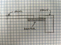
There are several options, the simplest being to support the panel by joining it to the baffle with a strip of damping material across a gap, either as a membrane or as a rolled edge, instead of layering behind. Similarly if the damping material is thick and soft, support the panel with a layer between the panel edge and the baffle edge, again to maximise strain on the damping material.
See below. Damping material goes across gap as membrane or rolled edge, or fills the gap itself between the edges of the baffle and panel. In any case, the damping material is subject to greater stress (shear stress) than sandwiching it between baffle and panel, where it is subject to relatively less compression and tension stress.

I extracted the sodium polyacrylate from a nappy. I got about half a teaspoon I would guess, which swelled immediately to fill a wine glass when I added water. Very squishy and seemingly a good damper, judging by tapping on the glass. ('Tink tink' vs 'ding ding' - very scientific, sans anti-xylophone 🤣).
This is the same material sold as water retention crystals for pot plants.
This is the same material sold as water retention crystals for pot plants.
Excellent! I am just explaining to cousins what is our subject and experiences! How is it possible to extract it? Is it a kind of layer inside?I extracted the sodium polyacrylate from a nappy.
Thanks for the sketch Paul. It's not necessarily clear to me that either geometry (sandwich, or surround style) would result in more deformation and damping, but I think either could certainly work. Generally I think the sandwich style is easier to execute in practice, but something like the image below is one way the "surround" approach could be easily implemented.See below. Damping material goes across gap as membrane or rolled edge, or fills the gap itself between the edges of the baffle and panel. In any case, the damping material is subject to greater stress (shear stress) than sandwiching it between baffle and panel, where it is subject to relatively less compression and tension stress.
Eric

It’s in the form of fine crystals distributed through the cellulose fibres within the diaper. Just pull it apart and rub the fibres the fibres, and it falls off. Use a dish to catch as it goes everywhere. Or buy a large quantity from the garden store. I read that it’s possibly a carcinogen, but can’t be too bad if it’s allowed in diapers.Excellent! I am just explaining to cousins what is our subject and experiences! How is it possible to extract it? Is it a kind of layer inside?
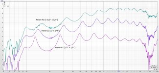
Concering the effect of the dimensions of the edge damping material, here are some examples.
For most of the materials I have been testing, making them wider increases the damping (flattens/widens the peaks) but pushes the natural frequencies higher. The example below is typical. In the chart, the first dimension is the width, second is thickness. Note, in these charts, ignore the first peak (at 100 Hz). It's not a natural frequency of the test beam. The exciter basically only works above 100 Hz,

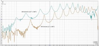
But one exception is the 3M Extreme mounting tape. Perhaps it's different because it is not a foam (or is very lightly foamed). For it, making it wider still pushes the natural frequencies up, but the damping gets worse (sharper peaks).

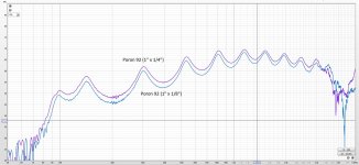
Interestingly, thickness has virtually no effect, at least in this comparison:

Eric
For most of the materials I have been testing, making them wider increases the damping (flattens/widens the peaks) but pushes the natural frequencies higher. The example below is typical. In the chart, the first dimension is the width, second is thickness. Note, in these charts, ignore the first peak (at 100 Hz). It's not a natural frequency of the test beam. The exciter basically only works above 100 Hz,

But one exception is the 3M Extreme mounting tape. Perhaps it's different because it is not a foam (or is very lightly foamed). For it, making it wider still pushes the natural frequencies up, but the damping gets worse (sharper peaks).

Interestingly, thickness has virtually no effect, at least in this comparison:

Eric
It might be worthwhile to compare sandwiched vs glued & sandwiched vs glued, no sandwich.
I read Poron 92 is slow rebound, so maybe this implies it's performance would be better stuck to the vibrating object, and to the substrate.
I read Poron 92 is slow rebound, so maybe this implies it's performance would be better stuck to the vibrating object, and to the substrate.
I probably just need to explain more clearly.I'm not sure what you mean exactly
My understanding of your current test procedure is to rest the ends of your wooden lath on top of the damping material to be tested.
My thought was simply that, for a material with a slow recovery time, the material may compress and not recover in time to follow the vibrating lath in the next half-cycle. Therefore my thought was that the performance might be improved by gluing the damping material to the lath and to the test bench. This would ensure that all parts of the damping material are in intimate contact with the lath and support, and remain so throughout the test.
It also occurred to me that once you go to the trouble of gluing, you may as well make another kind of test with a free end of the lath with and without damping. This is what I meant by 'glued, not sandwiched'
Paul
Paul,
My fault. I wasn't clear. In all the cases I've measured, the damping material was attached (i.e. "glued") by adhesive to both the frame and the test beam. Some of my materials have adhesive on both sides from the start, like the 3M mounting tapes and the butyl rubber glazing tape. Others have adhesive on one side (EPDM and others), and others on neither side (like the Poron foams). But in any case, I applied a double side tape to any any surface that didn't already have adhesive on it, to ensure that the damping material was firmly adhered to the rig on one side and the beam on the other.
I don't know what would happen if either side wasn't attached. Probably it would bounce itself right off the rig!
One thing I learned early is that some of the adhesives, like on the 3M mounting tapes, are strong enough to delaminate the face layer from my test beam. ****. So in some cases I started using a "sacrificial" layer of double side tape between the beam and the damper, even if the damper already had an adhesive layer. My double sided tape was a bit weaker than the adhesive, so I could dis-assemble the beam from the rig and damper without destroying the beam. I think that every result I have shared is with the exact same beam.
Eric
Last edited:
Executive Summary - Just read the bolded text 🙂
Hello all. I am late to the party but have been reading the three threads (damping, impulse, and DML full range) and several of the linked papers. For what it is worth I have been finding the discussion fascinating. I am a Mech Engr by training and profession though my work is implemented in a place with no sound (outer space) so I only know acoustics from amateur loudspeaker building. But I can relate to the fundamental engineering principles being shared here; I am basically trying to learn what the best practices are for DML design (to a reasonable extent) before I build my first.
@Veleric I think the dampophone is great and agree with your approach of looking at waveforms to determine the damping. This is exactly what we do when subjecting space payloads to the brutal random vibration test which is essentially a form of acoustic testing. There is a procedure for quantitatively determining the damping factor based on the shape of the fundamental responses particularly in sine sweep testing.
OK back to the matter at hand - edge damping. I think @pway is on to something with his gap damping approach. I agree that this would introduce more deflection in the viscous (damping) material, whatever it is, and thus it would absorb more energy. At any rate if you are willing I think a test on the dampophone of the 'gap' configuration that you and @pway showed in your sketches is worth a try.
One pitfall though is that there may (will) be a new mode created by the gap material acting as a spring (probably a soft one) and the whole beam moving as a rigid body normal to the plane. That would actually be a pitfall with the practical application as well unless that mode was designed out of the response region and then suppressed with a high pass filter. For example, design the rigid body mode at 20 Hz and then highpass the signal at 40 Hz or higher.
Also, since someone else raised the point about psychoacoustics and optimum damping... That is something I wondered about as well. For example, in TL design, there will be large but very narrow peaks in the modeled response (Martin's worksheets or Hornresp for example) that in practical application do not matter so much since we do not really 'hear' very narrow response peaks as much as one would think.
Whew... OK I'll be quiet now and get back to reading.
You know, the rigid body motion I describe above for the 'surround' approach could be advantageous; it could be used to augment the low end response if it were broad (low Q) and tuned just right. It would essentially be pistionic motion and act like an open baffle subwoofer (albeit without the baffle). Frequencies below the pistionic region may need to be HP filtered to stop overexcursion. Above the pistionic motion frequency the response may naturally roll off as it transitions to DML response.
Like this... Borrowing from @Veleric 's plot...
Like this... Borrowing from @Veleric 's plot...
Attachments
Last edited:
Here is the method for calculating the damping factor using the half-power method. Note it assumes that there is not significant overlap from adjacent modes which can alter the results. More details in the attached paper.

The other way to do it is to plot the transfer function directly from the response (if the software is capable) and then read Q straight from the plot, and calculate the damping factor from Q (easy).
The other way to do it is to plot the transfer function directly from the response (if the software is capable) and then read Q straight from the plot, and calculate the damping factor from Q (easy).
Attachments
Last edited:
- Home
- Loudspeakers
- Full Range
- Effect of Boundary Conditions on the Ringing of DML Speaker Panels
